
Modern automated process control systems require a significant amount of diversity of the measurements to ensure the production of signal measurement information in a form suitable for remote transmission, collection and subsequent transformation, processing and reporting it. The automatic control of key parameters the blast furnace process is a complex set of sensors, transducers, and the secondary instruments.
The introduction of automated methods of process increases the requirements for accurate measurement of individual parameters of these processes. The extensive range of measurement requires the correct choice for their specific purposes.
The widespread use of computers to solve information problems APCS and to calculate the technical and economic performance of the equipment determines the application of such methods and means of measurement, which in certain conditions would ensure the specified accuracy and allow for technological personnel of operational information and implement mathematical models of blast furnace control.
Temperature - a key parameter processes metallurgical industry. Therefore, the quality of temperature control often determines the success of the production process. In this regard, the most important tasks is to develop reliable methods of temperature control, the creation of automatic control systems, stability and performance. Currently, the system automatically controls the heating blower, developed by Siemens, provides information on stoves and heat control unit operation under optimal conditions [1].
The scheme of the existing automatic control system for heating the heater is shown in Figure 1. Gas stoves for heating the furnace enters the pipeline - one in which the orifice plate is installed. A standard set of instruments - 2 provides registration total amount of gas consumed for heating stoves of all of the blast furnace. The gas pressure is stabilized local template control system - 3.
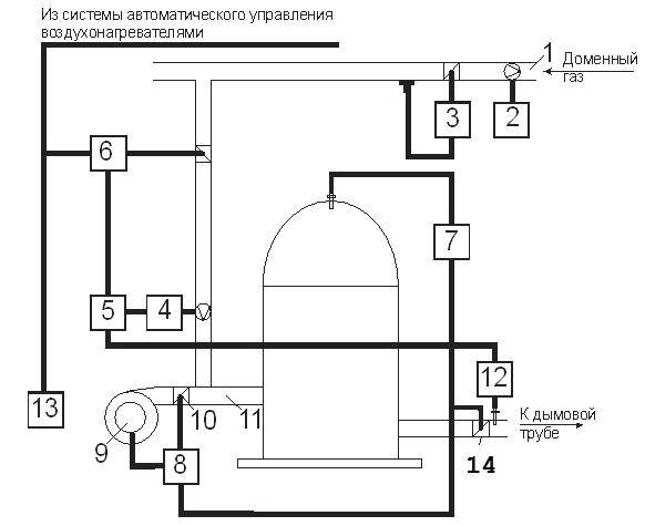
Gas consumption for each heater is controlled by a standard set of instruments - 4 and maintained at a given level of flow control - 5, which controls the actuator - 6 at the regulating valve, installed on gas supply to the burner.
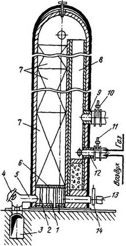
Canopy temperature stabilizes the system - 7, consisting of a temperature sensor, the secondary device, controller and actuator - 8, which acts on the damper louvers - 10 on air duct burners - 11 and the throttle valve regulate the flow of hot blast into the blast furnace - 14. Smoke temperature measured by thermocouple and a secondary device - 12 [3].
Job Management System by heating the heater runs as follows: from the scheme of automatic translation heater receiving signals to activate the fan and the partial opening of the valve on the gas burner. If the combustion chamber heater break out the torch, the sensor - 13, gives permission for the inclusion of an automatic regulator - 5, which supports the desired gas flow rate. Air consumption at this point is set so that the air flow rate was close to unity. Dome heater temperature begins to rise and at some point of time reaches the maximum value. Since then, the regulator - 7 begins to increase airflow by opening the blade guiding apparatus. The temperature of the dome is stabilized by reducing the temperature of combustion and heat transfer from gases to the nozzle heater is growing as an increasing number of products of combustion and increases the speed of their movement through the nozzle [7].
As the heating nozzle increases the temperature of the smoke coming from the heater. When it reaches the maximum allowable value, temperature control system of smoke - 12 starts to adjust the reference gas flow controller - 5, reducing the task so that the smoke temperature did not exceed the maximum value. Air flow is not changed, so the correction system operates very effectively. If the temperature of the dome will be somewhat lower, then the stabilizer will reduce the temperature of the air flow, which will also reduce the rate of air flow and thus increase the temperature of the upper part of the heater [4].
Analysis of the control system heating stoves showed that out of all control system air heater, the lack of a system of temperature stabilization of the dome - 7, consisting of a temperature sensor, the secondary device, controller and actuator - 8, which acts on the damper louvers - 10 at the air duct burner - 11.
On the basis of these deficiencies automatic temperature control system in the previous section, it is proposed to develop a new automation system based on an existing one. The scheme developed temperature control system of the dome heater is shown in Fig. 2.
At the heart of the system being developed on the principle of regulation of supply of cold air in the dome when the heater is overheated due to the expense of speed control short-circuited induction motor of a centrifugal fan. Depending on the temperature of the dome, the controller will generate the necessary signals to control the motor for its stabilization. In this setup, stepless motor speed will eliminate the use of chokes, valves, dampers, actuators and other control equipment. This greatly simplifies the mechanical system, improves reliability and reduces operating costs, and costs associated with the acquisition of control apparatus. When connected via a frequency controller, start the engine takes place gradually, without inrush currents and shocks, which reduces the load on the engine and tools, prolongs engine life. Using a variable-frequency electric permits to get energy savings of up to 50%. Energy conservation occurs while eliminating non-production costs in the regulatory devices (grills, shutters, chokes, valves). You can use cheap domestic standard electric motors with a speed of 950 rpm. Due to the introduction of frequency control and built-in PID - controller, we have the opportunity to achieve the required speed at a constant force on the shaft, which provides, in turn, the gradual regulation of fan speed and the exact observance of the temperature of the blast [5].
When adjusting the speed of the electric drive, frequency and output voltage frequency converter varies in accordance with changes in temperature of the dome heater. By varying the frequency, can be a wide range, adjust the speed of the motor shaft. At the same time slipping the induction motor in the regulatory process, at a given load varies only slightly, and hence the losses in the rotor circuit are proportional to slip, too, vary slightly, which enhances energy efficiency [6].
The study of thermal processes stoves of blast furnace was disclosed urgency of the chosen topic, the analysis of the process of heating the blast in a blast furnace air heater, examples of existing technical solutions as well as their own results to develop a means of temperature control to improve the automatic control system. The proposed system meets the technical, metrological, dynamic and operational requirements to the object and can be used as a dynamic link of the automatic control system with the continued use of measurement information to control the operation of blast furnace stoves. This system controls the heating of the dome of the heater in the desired range by adjusting the temperature automatically blast.
When writing this abstract of master's work is not yet completed. Final completion: December 2011. The full text of work and materials on the topic can be obtained from the author or his head after the specified date.