Источник: http://citeseerx.ist.psu.edu/viewdoc/download?doi=10.1.1.90.1639&rep=rep1&type=pdf
Abstract
This paper wishes to introduce new concepts to be applied for future Internet generations. These
concepts are based on the introduction of some intelligence in a policy-based networking environment.
We first describe a policy-based networking environment and some new protocols allowing an easy
control of the QoS and the mobility. Then, we describe the I3 platform able to support some
intelligence to help the policy-based networking environment to react, manage and control future
Internet networks.
1. Introduction
Internet I1 is the first generation: the system that we reach today from our terminal. I2, Internet second
generation: we entered there in the year 2000. I3 is arriving and the first concepts are born. I1 comes
from the initial work of some tens of scientists in the world believing in a universal system. During
80s, academic centers exchange messages by the "Net". The period 1990 to 2000 defines the arrival, in
the public, of commercial offers allowing communicating with high-speed servers supporting services.
However, throughputs are too slow, servers do not deliver the desired information, browsers surf
without end. At the end of the 90s, the promises of increase of the throughput are real; costs become
almost accessible, new innumerable and attractive service perspectives open. In the year 2000, I2
arrives with its high throughput, its procession of services, its best stability ahead breakdowns, its
quasi-universal access. Between 2005 and 2010, the passage to I3 would have to lead to a more stable
system, stabilized protocols, imperceptible breakdowns to the user, a large number of available
multimedia applications, and a generalized access.
What directions to push on? The intelligence. The system must be intelligent. The debate on the
computer intelligence is not new, but the distributed nature requires for an additional component: the
time. The system has to be able to adapt itself to a new situation, to control critical states and to
manage unexpected situations. Intelligence is the chosen word to group several actions well distinct: to
learn, communicate and infer. Several ways can be envisaged, with their own roots: intelligent
systems, smart systems (smart networks) and active systems. Intelligent systems form an already old
architectural concept where the intelligent word meant adaptation. The system has to be able to adapt
to the user demand. Even if some experiences were tested in telecommunication systems, we still are
only in the first steps. In this area, the data-processing could induce a too large delay when using
languages like Java, that disseminate pieces of software in a very large number of points. These pieces
of software can possibly move by themselves.
The second field is supported by smart systems. It is necessary to develop specific components to
bring their expertise to solve problems and to control infrastructures and flows. As a first answer, there
are some known solutions: they come from the intelligent agents field. An agent is an autonomous
entity able to communicate with others agents, to perceive and to represent its environment. The whole
agents in interaction form a multi-agent system. Many criteria allow to classify these systems: the size
of agents, the number of agents in interaction, the mechanisms and the types of communication, the
behavior, the organization and the representation of the environment.
The third area corresponds to active networks. The intelligence in active networks, situated inside the
nodes of the system, as well as in the user workstations, can adapt the nodes and the workstation to the
type of information received. For example, the header of the packets can contain programs that must
be executed in the routers. The nodes have to fit instantaneously to the arriving packet, what seems
possible with new reconfigurable processors.
I3 researches focus on the intelligent control of the system: I3 is based on an intelligent platform. The
basic problem concerns the architecture of the system to integrate the "intelligent" components, so that
they could be simple and cooperating.
This paper presents the development of an intelligent platform based on a policy-based networking
system. Section 2 introduces policy concepts. Section 3 is dealing with a new protocol for controlling
the configuration of hosts. Section 4 introduces mobility management within the global system, also
using the policy-based networking paradigm. Then, section 5 is introducing the I3 platform. Finally,
the I3 model is developed.
2. An Introduction to Policies
Policies can be defined as a “set of rules to manage and control access to network resources”. The
works dealing with policies come from different domains, sharing common needs. The most advanced
works are found in the quality of service (QoS) domain, with the definition of a new protocol (COPS)
and a new architecture. To make this specific approach more general, a working group has been
created by the IETF to specify the information model to be used, as well as the general architecture.
The goal of the information model is to define a general model that can be specialized into different
domains, independently of any equipment or implementation.
The Policy Core Information Model (PCIM) is an extension to the DMTF CIM model. The network is
seen as a state-machine, policies being used to control state changes. It must be able to identify/model
the current state (objects) and define possible transitions (rules). This model simply defines rules as a
set of conditions and a set of actions. An action is being activated when a rule condition is verified.
The model includes a few more elements, to be able to define roles, priorities and execution order, but
stays in a quite abstract form concerning objects.
Current works around QoS define two levels of extension: the QoS Policy Information Model (QPIM)
and the QoS Device Datapath Information Model (QDDIM). The first one integrates QoS specific
notions, to be able to create formal representations of abstract policies, such as: “If packet’s protocol is
http and its destination is in the EXECUTIVES user group, then assign IPP 7 to the packet header”. To
this aim, the model defines Policy Actions (RSVP, provisioning, PHB) and traffic profiles, to specify
processing to be done on requests and flows. The QDDIM model extends the previous one to define
actions to be done on the equipments (configuration), where QPIM defines actions to be done on
packets.
The architecture defines a centralized model for management, policies storage, decision-making, and
configuration distribution. This architecture is described in Figure 1.
The PDP is responsible for making decisions, to its own initiative, or by reacting to a request from a
network element. It has to determine which configurations need to be applied to the resources to
satisfy the network policies. The main functions deals with the determination of what rules are
relevant to the different PEPs, the conversion in an adapted format (PIB, MIB, etc.) and the guarantee
of their right distribution.
A PEP is a logical entity that enforces policy decisions. It corresponds to a resource offering services
that can be used to apply network policies. Main functions of a PEP consist to link the external
representations (PIB, MIB, etc.) to the internal equipment configurations, and to maintain local
policies integrity while monitoring their enforcement. When integrated in an admission control entity,
the PEP is also responsible for validating the requests (ex. RSVP) by soliciting the PDP.

Figure 1 – Policy-based management architecture
The architecture model does not require any specific communication protocol or storage method for policies. Nevertheless, the COPS protocol and directories using LDAPv3 seem to be the preferred ways.
3. COPS and COPS-SLS
3.1 COPS protocol
COPS (Common Open Policy Service) protocol [1] is a TCP-based protocol proposed by Resource
Allocation Protocol working group of IETF to convey policy information between the PEP and the
PDP. The PEP is the policy client and the PDP is the policy server. When the PEP wants to know
policies to manage network resources, it sends a Request (REQ) message to the PDP. Upon receipt of
the Decision (DEC) message from the PDP, it enforces network policies.
Two models are defined in policy control: Outsourcing model and Configuration model [3]. In
Outsourcing model, the PEP does not know policies before the arrival of a resource request event.
When a resource request arrives, the PEP sends a REQ message to the PDP to obtain the decision to
accept or reject this resource request. In Configuration model, the PEP installs policies before the
arrival of resource request event. When a resource request arrives, the PEP enforces without sending a
REQ message to the PDP.
COPS protocol itself defines only messages for general purpose for policy information transport. In
each domain, where COPS is used for a specific purpose, an extension must be defined and
distinguished by the Client-Type field in the common header of COPS message. There are many
extensions of COPS protocol but only COPS-RSVP [4] is assigned by IANA with a ‘Client-Type = 1’.
Other extensions are currently works in progress. For example, COPS-PR for DiffServ router
configuration [5], COPS usage for IP Traffic Engineering [6], COPS usage for IPsec configuration [7],
etc.
3.2 COPS -SLS
COPS-SLS [2] is an extension of COPS protocol. The idea of COPS-SLS is to apply Policy-based
networking in SLS negotiation. This extension gives I3 platform a means to negotiate dynamically
between a client and a network provider about client’s needs, such as QoS parameters, security,
mobility, etc. Figure 2 presents the COPS-SLS model.
The SLS-PDP entity represents the network provider and the SLS-PEP entity represents the client. The
client may be an end-host (connected to the network via a modem), or a gateway of a local network, or
another ISP. The client here is just a logical entity who requests, possibly on behalf of other entities,
network resources.

Figure 2 - COPS-SLS model
COPS-SLS comprises two phases: Configuration phase and Negotiation phase. The organization of
SLS negotiation process in two phases makes the negotiation very dynamic. The Configuration phase
decides how the Negotiation phase takes place. For example, the network supplies the client with
information about the negotiation mode, time interval to renegotiate, PIB classes to be exchanged, etc.
[2]. After successfully installing the configuration supplied by the PDP, the PEP can start the
Negotiation phase by sending a request for its desired level of service. The PDP can accept or reject
the request or propose another level of service to the client. At any time, the network can send an
unsolicited decision to change the parameters of the Negotiation phase. This phase will be guided with
the updated configuration.
SLS information exchanged between the PEP and the PDP is represented by a named data structure,
a.k.a. a PIB [3]. The use of a PIB for a SLS representation gives a possibility to take into account all
desired negotiation parameters of all providers. Common classes may be used to specify common
parameters of the service and private classes may be used by network providers to personalize their
SLS parameters.
4. Mobility and COPS-MU
In order to unify the network management process, we suggest extending COPS usage for user
mobility management in IP networks. User mobility [8] concerns the terminal mobility and the
personal mobility, which is the ability of the user to use different terminals and access his personal
services in his home network from anywhere [9].
We identify four issues in the user mobility management which are: terminal registration, user
registration, services portability and QoS negotiation We propose to have a policy enforcement point
on the terminal called TPEP which interacts directly with the Foreign PDP (FPDP) for terminal
registration, user registration, services portability and QoS negotiation.
4.1 Terminal and user registration
Terminal registration must be achieved only if a terminal is located in a foreign network, if it is a fixed
terminal or a mobile terminal located in its home network then terminal registration is not needed. A
user registration must be achieved every time a user logs in a terminal even if a user is in his home
network.
Terminal registration consists of maintaining an association in the Terminal Home Agent (THA)
between the terminal Care of Address (CoA) and its home address. User registration consists of
maintaining an association in the User Home Agent (UHA) between the user identifier and the IP
address of a terminal he is using. The user mobility binding allows to the user to be reachable on the
terminal he is using, and to use subscribed personal home network services from anywhere. The later
deals with service portability management.
Steps explained below are the suggested steps for policy based terminal and user registration
management illustrated in Figure 3:
1. TPEP interacts directly with TFPDP (rep. UFPDP) for terminal (resp. user) registration
request policy decisions;
2. Mobile Terminal (MT) sends registration request to the TFA (resp. UFA);
3. THPEP (resp. UHPEP) interacts with THPDP (resp. UHPDP) for terminal registration
request;
4. HA sends registration reply message to the MT;
5. TPEP interacts with TFPDP (resp. UFPDP) for terminal (resp. user) registration reply policy
decisions.
In this scenario the terminal has a co-located CoA such as in IPv6. If the terminal has a CoA, it
achieves it registration through the FA [10].

Figure 3 - Policy based terminal registration.
4.2. Service portability
Service portability is related to using personal home network services from anywhere and from any
terminal. Third generation of mobile networks deals with service portability using Virtual Home
Environment (VHE).
We suggest using a policy concept to deal with service portability in IP networks. Thus, TPEP has to
interact with FPDP, UHPDP, and THPDP for service portability and QoS negotiation. This negotiation
may be achieved either at a same time with the terminal and user registration or, at any time when a
user needs to use a home or a foreign network service.
In a wireless network access we have to minimize traffic on a wireless link. We suggest reporting
negotiation process in a fixed part of a network. TPEP interacts only with one PDP; either a HPDP or
a FPDP, and make PDPs negotiating to support the user requests for service portability.
Figure 4 illustrates personal home network service portability negotiation. Numbered steps on this
figure are explained bellow:
1. TPEP interacts with a UHPDP for service portability. TPEP sends to a UHPDP:
- the terminal profile;
- the required home service.
2. UHPDP interacts with its UHA to determine the required user service features using user profile
services. UHPDP based on previous criteria interacts with FPDP and THPDP to decide where to carry
out a required home service. FPDP sends to UHPDP its:
- network access features which are related to the QoS that may be offered by a fixed or wireless
network;
- foreign network access resources and services cost.
THPDP sends to UHPDP the terminal profile if it is not sent by the TPEP.
3. Based on UHPDP policy decisions, UHPDP may interact with UHPEP to configure its local
resources using UHPEP to provide user home services in the home network, FPDP may interact with
FPEP to configure its local resources to support personal home service portability, and THPDP may
interact with TPEP to configure the MT to support personal service portability.

Figure 4 - Policy based services portability management.
QoS parameters defined in fixed networks are: bandwidth, delay, jitter, and, packet loss. User mobility
also defines other parameters related to mobility management such as packet loss due to handoff, and,
handoff blockage probability. When a MU needs to use one service with a required QoS, the TPEP
interacts with the FPDP for QoS negotiation.
In the policy based user mobility management we need to define these objects:
- Objects defined in Mobile IP related to terminal registration;
- New Objects defined in extended Mobile IP to support user registration;
- New Objects defined to transport terminal parameters, access network parameters, personal services
parameters, user mobility behaviour for service portability and QoS negotiation.
It is important to note that COPS support security mechanisms such as authentication and data
integrity. These features are interesting in the user mobility management. Paper [11] suggests that the
authentication procedure for Mobile IP can be achieved by another entity than HA or FA. In our
model, we suggest that the authentication procedure will be supported by the policy server PDP. Thus,
we have to define authentication objects to achieve TPEP/FPEP-FPDP, TPEP/FPEP-THPDP,
TPEP/FPEP-UHPDP authentication.
Presently, we are defining a new PIB (Policy Information Base) [12] to support mobile user policy
objects structure.
4.3. Conclusion
We believe that the use of COPS and PDP/ PEP model offers a good way to achieve IP network
management. In the case of user mobility, it could allow the deployment of universal personal
computing policy control in IP networks by offering policy based network providers negotiation for
user and terminal management, service portability, and QoS negotiation.
Future work intend to define all necessary policy objects related to user mobility registration, terminal
mobility registration, service portability, and QoS negotiation. We aim to define a PIB to structure
policy objects needed to address all these issues. Finally, related work in I3 research project is defi ning
PDPs negotiating process.
5. AALAADIN Model and MADKit Platform
AALAADIN is the organizational description model that structures MADKit platform. This model is
based on three main abstractions (Figure 5)
1. Agent
There are no constraints on the internal architecture of an agent. An agent is just specified as an active
communicating entity, playing roles within groups. This definition is left general to allow agent
designers to adopt the most accurate definition of "agenthood" according to their application. The
agent designer is responsible for defining the most appropriate agent model he needs.
2. Group
Groups are defined as the smallest agent aggregation. An agent is part of one or several groups. The
group is only a way to tag a set of agents. In a more developed form, in conjunction with the role
definition, the group may represent any usual multi-agent system. An agent can be a member of
several groups at the same time. Moreover, AALAADIN groups can freely overlap. Any agent can
found a group, and an agent must request its admission to an existing group. Groups might be
distributed among several machines.
3. Role
The role is an abstract representation of an agent function, service or identification within a group.
Each agent can own several roles, and each role handled by an agent is local to a group. As with group
admission, handling a role in a group must be requested by the candidate agent, and is not necessarily
accepted.
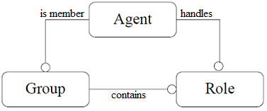
Figure 5 - AALAADIN model basic abstractions
To communicate, two agents should own a role within the same group. But it is possible to
communicate through agents, as shown in Figure 6. In this example, agents A and D cannot directly
communicate. Agents A and B own the same group 1 and then are able to communicate directly.
Agents B and C own the group 2, and agents C and D the group 3. Then, it is possible to make
communicating agents A and D through agents B and C, according to the established hierarchy.
It is worth stressing that an agent can be a member of at least one group, a group contains at least one
role, and an agent plays at least one role within one group.
MADKit stands for "Multi Agent Development Kit". It is an agent platform developed at LIRMM
laboratory. Written in Java, this platform is easy to use on several system environments.
MADKit is based on AALAADIN organizational model to manage its agents. MADKit platform has
been chosen to implement the prototype of I3 project for two main reasons. MADKit agents allow
adding some intelligence within network elements and the organizational model makes easier the
handling and management of network streams. An agent is a small program written in Java. MADKit
platform is used through an API (Application Programming Interface) providing classes and methods
allowing an organizational management of the agents. Abstractions as "group" and "role" help during
the creation of the agents, giving them a logical role. Classes of MADKit API make easier the
communication between agents. For example, it is possible to broadcast a message to all agents of a
given group, or to all agents owning the same role within a given group. Other Java methods are
defined to ensure the management of roles (add, remove, etc.).

Figure 6 - Inter-agents communication
6. The I3 Model
The aim of I3 project is to put within the core network some intelligence to get easier its management.
This intelligence will be introduced through agents in network equipments.
In the project, each flow associated to a client is characterized by a profile. The definition of a profile
is quite similar to SLA notion, but goes beyond the classical vision characterizing a traffic flow.
Indeed, a profile, characterizing the client's needs, contains a set of requirements: QoS parameters,
security needs, mobility requirements, …
6.1. A Functional Architecture supporting QoS
In order to support good end-to-end QoS in Policy-based networking systems, we propose the
functional architecture shown in Figure 7. There are four main parts in this architecture: Contracts
Management, Network Management, Policy Management and Monitoring.

Figure 7 - The Functional Architecture
Contracts Management is responsible for all contracts-related activities and includes two functions:
Contract Subscription and Contract Invocation. Contract Subscription is responsible for customer
registration and policy-based admission. The customer might either be an autonomous system, a PDP
of another domain or a residential customer. Contract Invocation is in charge of admission control as
requested by the user.
Network Management is responsible for mapping the traffic onto the physical network resources and
configures the network according to the contract. Two sub-functions may be determined: routing and
resource reservation.
Policy Management includes functions such as Policy Management Tool and policy Storing Service.
Finally, Monitoring provides information about the resource usage and the quality of offered services.
Monitoring has not only a diagnostic role but also it has a pro-active/reactive operational role [13, 14].
6.2 Agent Model
In our model, we want to place some intelligence in the core of the network to simplify management
operations. This intelligence will be introduced into the network's core equipment by agents organized
through multi-agents systems (MAS). In this way the network will be more reactive to problems that
could happen. The system includes reactive and cognitive agents.
We define a structure of activation for this MAS, which consists in obtaining information on the
environment, and activating some intelligent components of the system. This structure might be seen
as an organization of reactive agents built through 3 classes:
· The interface agent that collects information on the external world, then transmits them to;
· The activation agent that receives collected information and applies a filter to these data, and
transmits them to;
· The motricity agent that controls the system following the decisions engaged by the cognitive
agent.
The PEP constituting the point of application of the policy and playing the role of police officer will
be seen like an agent (reactive). This agent controls the components of the system; it is an agent of
motricity in our system of activation. The PDP constituting the decision-making system of the rules,
and playing the role of the judge will be seen as a cognitive agent. This cognitive agent evaluates the
various policies enabling him to satisfy these goals. For example to provide a good QoS.
To give life to the functional architecture we described previously, this architecture will be represented
by a MAS to introduce some intelligence. Each agent will be responsible for a function of the
architecture.
6.3. I3 platform model
Figure 8 represents the AALADIN model of the I3 platform. Each "I3 router" is considered as a PEP.
The PDP handles the management of network resources and the enforcement of decisions within the
PEP so that the client (flow) requirements are satisfied. The I3 router model includes the following
components:
The StreamAgent
The StreamAgent, associated with each flow stream, is defined to handle the flow during the
communication live time. The main goal of StreamAgent is to provide the platform with information
about flow requirements (QoS, security, mobility). For each requirement a group is defined. Thus, if a
flow needs a given requirement the corresponding StreamAgent owns a given role within the
corresponding group. For example, the StreamAgent could have a "maximum_security" role, in a
security group, and a "low_mobility" role, in a mobility group. These roles characterize the stream,
making easier its management. The set of flows having the same requirements are aggregated and
managed by the same agent i.e., the ManagerAgent.
The ManagerAgent
The ManagerAgent, defined in each group, has to collect information about the needs of aggregated
streams, and forward them to InformationAgent of "Manager" group. The main goal of "Manager" group provides the platform with the ability to handle dynamic changes of service requirements, which
may occur during the communication live time. In other terms, if, during the communication, the
needs change, the ManagerAgent informs the PDP server (via the InformationAgent) about these
changes. The PDP, according to the availability of resources, defines new policies so that the new
requirements are fulfilled.

Figure 8 - I3 platform model
The InformationAgent
The InfomationAgent has a global vision about all client's needs. It submits the service request to the
PDP server via a "Policy" and "PEP" groups. The PDP Server decides on the policies to be enforced to
satisfy the needs. In particular, the decisions may concern resource allocation. In this case, the request
is taken in charge by the AllocationAgent and forwarded to the ResourceAgents, which represent the
network resources.
The MonitoringAgent
The MonitoringAgent is the manager of the "monitor" group, which contains Agents for collecting
indicators of QoS.
6.4. The PDP model
It is worth stressing that the PDP server is a remote entity. Thus, the communication between a PEP
and a PDP does not take place in the same group. Intermediate agents, i.e., PEPCoreAgent and
PEPInAgent, which communicate via COPS messages, are defined.
The InvocationAgent that belongs to PDPClient group performs the admission control of a customer
who asks for a given service. It consults the "Repository " to see whether this customer is authorised to
have the service with the desired quality. The ServiceAgent is responsible for the customers with new
contracts of service; it introduces the terms of the new contract like an entry into a predictor of
contract.
In the PDPMonitor group, the SLSAgent takes care of the respect of the contract of service. The
NetAgent is responsible for the monitoring of the network and its resizing.
The PDPNet group contains the agents responsible for the routing and resource allocation.

Figure 9 - PDP Model
6.5. The client model
In addition to the model defined for the PDP/PEP enironment, we propose a client model (see Figure 10) for the choice of the provider. Indeed, the main problem encountered by the operators and providers is at the level of their access network that generally constitutes the bottleneck. We retained the protocol called "Contract Net" based on the concept of contracts between Providers (ISP) and consumers (Customer) of services. We have introduced a broker which is connected to all the providers and who plays the role of an edge router. Thus each customer knows only the address of the broker.
Figure 10 - Agent Model
In this model, provider agents take suitable roles in the Provider-Group according to their competence, and attribute prices for their Services. An Agent Broker joints the Client-Group group and the Provider-Group. When a customer wants to make a request for service with a given QoS, a Client agent joints the Client-Group group with the role of member. It seeks for the Broker role, and asks him to find the best offers for the requested QoS (for example, a Gold, Silver or Bronze Assured Forwarding service in DiffServ). The broker agent interacts with the provider concerned with the Provider-Group, chooses the best offers and transmits information to the Client and to the selected Provider. Then, these two agents create their own Contract-Group group to sign the contract.
7. Conclusion
This paper introduced new concepts that could be applied for future Internet generations. These concepts are based on the introduction of some intelligence in a policy-based networking environment. We proposed a policy-based networking environment supporting new protocols compatible with COPS and simplifying the control of the QoS and the mobility in the IP network. Then, we describe the I3 platform able to support some intelligence to help the new policy-based networking environment to react, manage and control future Internet networks. Future works will concern authentication and more generally the security to be provided in the future IP networks.
Reference
[1] D. Durham, Ed., J. Boyle, R. Cohen, S. Herzog, R. Rajan, A. Sastry, “The COPS (Common Open Policy
Service) Protocol”, RFC 2748, January 2000.
[2] T.M.T. Nguyen, G. Pujolle, N. Boukhatem, “COPS Usage for SLS negotiation (COPS -SLS)”, draft-nguyenrap-
cops-sls-00.txt, work in progress, June 2001.
[3] K. Chan, J. Seligson, D. Durham, S. Gai, K. McCloghrie, S. Herzog, F. Reichmeyer, R. Yavatkar, A. Smith, “COPS Usage for Policy Provisioning (COPS -PR)”, RFC 3084, March 2001.
[4] S. Herzog, Ed., J. Boyle, R. Cohen, D. Durham, R. Rajan, A. Sastry, “COPS usage for RSVP”, RFC 2749,
January 2000.
[5] M. Fine, K. McCloghrie, J. Seligson, K. Chan, S. Hahn, C. Bell, A. Smith, Francis Reichmeyer, “Differentiated Services Quality of Service Policy Information Base”, draft -ietf-diffserv-pib -03.txt, work in
progress, March 2001.
[6] C. Jacquenet, “A COPS client-type for IP traffic engineering”, draft -jacquenet-ip-te-cops-02.txt, work in
progress, June 2001.
[7] Man Li, David Arneson, Avri Doria, Jamie Jason, Cliff Wang, “IPSec Policy Information Base”, draft-ietfipsp-
ipsecpib -03.txt, work in progress, July 2001.
[8] E. Koukoutsis, C. Kossidas, N. Polydorou, “ User Aspects for Mobility”, Acts Guideline SII-G8/0798.
[9] A. Fasbender,F. Reichert, E. Gueulen, J. Hjelm, T. Wierelemann, “Any Network, Any Terminal, Anywhere” IEEE Personal Communications 1999.
[10] C. Perkins, “IP mobility support”, RFC 2002, October 1996.
[11] L. Bos, S. Leroy, “Toward an All-IP-Based UMTS System Architecture”, IEEE Network, January 2001.
[12] B. Moore, et al, “Policy Core Information Model”, RFC 3060, February 2001.
[13] Tequila, "A Management and Control Architecture for Providing IP Differentiated Services in MPLS -Based
Networks", IEEE Communications, May 2001.
[14] Tequila, "A Monitoring and Measurement Architecture for Traffic Engineered IP Networks ", IEEE
Communications, May 2001.