Abstract
As more and more powerful graphical processors become available on mainstream computers, it becomes possible to investigate the design of visually rich and fast interactive applications. In this article, we present SVGL , a graphical toolkit that enables programmers and designers of interactive applications to benefit from this power. The toolkit is based on a scene graph which is translated into an optimized display graph. After describing the algorithms used to display the scene, we show that the toolkit is two to fifty times faster than similar toolkits.
Key words: 2D GUI, fast rendering, visually rich interfaces, Post-WIMP, OpenGL, scene-graph, SVG.
1 Introduction
Today applications use Graphical User Interfaces (GUI) based on a 20 years old model introduced with the Xerox Star, and coined Windows, Icons, Menu, Pointing (WIMP) interfaces. Since then, researchers have designed new paradigms — altogether known as post- WIMP interfaces [19] — for interacting with applications, such as Zoomable User Interfaces (ZUI), seethrough tools, or dynamic queries.
However, even if some of these work have turned into commercial products, they address a niche market and are seldom found in everyone’s computer. Post-WIMP interfaces require a lot more computational power than traditional ones, either because they are aimed at visualizing large amounts of data, or because they use demanding graphical techniques such as transparency.
Our main goal is to design a toolkit to enable interface designers to actually use novel interaction techniques. As a first step into this direction, we have developed SVGL, a toolkit that provides both a visually rich graphical model and a fast rendering engine. The toolkit is based on a scene graph that describes the elements to be displayed and their graphical attributes. Instead of designing our own scene graph, we have chosen to use SVG (Scalable Vector Graphics 1) for three reasons. First, it is a vectorbased format: it describes graphical primitives in terms of analytical shapes and transformations. Second, an SVG scene is a directed acyclic graph (DAG) that can be analyzed and transformed for optimization purposes. This contrasts with traditional GUI toolkits such as Motif[7], where no optimization is performed at the widget tree level. Finally, SVG has been designed by professional graphical applications companies, such as Adobe, and provides a very rich graphical primitives set. Hence, most commercial drawing and painting software can produce graphics that SVGL can display natively, allowing graphic artists to be more involved in the design process of interactive applications.

Figure 1: A rich SVG document, edited with a translucent toolglass. The tiger is rendered at 200 fps on a 1Ghz P3 + GeForce 2 GTS.
To address the computational power issue, the toolkit translates the SVG DAG into hardware-accelerated graphical primitives supported by the OpenGL library. Relying on a graphical hardware acceleration has two advantages: first, a graphical processing unit (GPU) is 10 to 100 times faster than a multi-purpose processor at displaying graphical primitives; second, the rendering process is mostly deferred to the GPU, freeing the CPU for other computational tasks.
Displaying an SVG scene with OpenGL is not a straightforward task. Problems arise in the translation of high level SVG primitives into low level OpenGL ones: OpenGL offers a limited set of low level operations, and the choice of possible translations greatly affects the performance of the rendering process.
This article begins with a description of related works designed to address some of the mentioned issues. The second section briefly describes the OpenGL API and the SVG format. The third part explains the main characteristics of the toolkit in terms of graphical primitives, how they can be translated into OpenGL calls and how using a scene graph allows the toolkit to accelerate the rendering. The last part discusses the results of benchmarks comparing SVGL to related systems.
2 Related Work
SVGL is a high level 2D API based on a scene graph of lightweight 2D objects. As such, it is related to “retainedmode graphics” APIs used in the 3D graphics community. It is also related to recent 2D scene graph APIs or systems from the 2D community. We describe these two families of APIs in this section.
2.1 3D Retained-Mode Graphics APIs
Retained-mode graphics packages are defined in [8], p. 293: ”It keeps a record of all primitives and other related information to allow subsequent editing and automatic updating of the display, thereby offloading the application program.” It opposes to “immediate mode” graphics where the application is in charge of sending graphical primitives to the display. OpenInventor [13] and Java3D[18] are probably the most popular retainedmode 3D toolkits.
OpenInventor maintains a DAG of graphic components organized as a hierarchy. Components can be graphic attributes, geometrical transformations, shape descriptions and interaction managers called Draggers. With this structure, displaying a scene consists simply in a preorder traversal of the DAG, each visual component being sent as a primitive to OpenGL – OpenInventor being specially designed for OpenGL. In addition, OpenInventor provides a data-flow mechanism to connect values together and trigger their re-computation when some events happen. It also provides a file format to store and load scenes. Finally, by documenting and exposing the scene graph, OpenInventor programmers can analyze and optimize it in a portable way, leading to several optimization packages.
Java3D is a 3D toolkit available for the Java programming language since June 1999. It is inspired from Open- Inventor but has notable differences with it. First, it completely hides the immediate mode graphics under it and supports the two popular low-levels API (OpenGL and DirectX). Second, it relies on an explicit compilation of the scene graph. Application starts by building the graph and specifying which values they want to change or read after compilation. They then call the “compile” method on the graph before being able to display the result. The actions performed during the compilation process are hidden but meant to rewrite the scene graph into an optimized version where some computation have been performed at compile time.
OpenInventor and Java3D are 3D toolkits. We decided not to use them mostly because 2D drawings allow for optimizations that do not fit well with a 3D-based model. Furthermore, OpenInventor has some features, such as active variables, that add a lot of overhead. Java being too slow on many platforms, we decided not to stick with this language with Java3D. However, we plan to include the optimizations used in both toolkits in SVGL.
2.2 2D Scene Graph APIs
Most popular 2D APIs are component based: applications construct their graphical output by combining interactive components that have a look and an interactive behavior. Changing the appearance or behavior of these components is usually as hard as creating new components. Popular component based APIs such as Motif[7] or MFC[16] propose now several hundreds of components, each having a specific look and interactive behavior. The graphic quality of the look is always limited by the graphic primitives and attributes of the underlying immediate mode graphics model (and by the talent of the designers).
In the early nineties, Linton at al. have designed the InterViews and Fresco toolkits [12, 11] to separate the appearance from the behavior through “lightweight graphical objects” organized as a DAG. Like OpenInventor “Draggers”, interaction is managed by special interactive objects inside the DAG. Therefore, the appearance of Fresco can be changed and enhanced independently of the interaction. However, these two toolkits rely on the graphics model of the windowing systems, which is limited to flat colors, no transparency and no general geometrical transformations. Fresco implements geometrical transformations in software, adding graphical capabilities at the cost of more computation and complexity. This complexity comes from the inability of the underlying graphic system to display transformed primitives. To display a text rotated by 10 degrees requires Fresco to re-implement most of the font rendering engine. While InterViews has been used by commercial graphic packages, Fresco remained a research work, now continued by the Berlin project.
Since the mid-nineties, scene graph have been used for Zoomable User Interfaces (ZUI) such as Pad++ [3], Jazz [4] or Zomit [14]. ZUIs need to manage navigation through panning and zooming, provide smooth animation and semantic zooming with continuous transitions. They rely on a scene graph to perform on the fly analysis for optimizations. They also use the DAG structure to offer multiple views of graphic objects through sharing and portals. In [2], Bederson and Meyer describe issues in implementing ZUIs and more specifically rendering issues. Their imaginary ideal Zooming Graphics Accelerator must have the following features (numbers are added to refer to the points later):
Text (1)High quality anti-aliased text which can be transformed and scaled rapidly;
(2) Support for a wide range of fonts, including Type1 and TrueType; [...]
Lines (3) A rich set of line drawing styles, including rounded ends, bevel, mitering and dashes;
(4) Scalable line width and semi-transparent lines.
Images and Movies (5) Hardware accelerated image scaling, preferably using filtering to produce smooth results;
(6) Support for MPEG and QuickTime digital movies which can be scaled to any size and played at 30 frames a second.
General (7) Two 24 bit color buffers (for double buffering), a 24 bit depth buffer, an 8 bit alpha buffer for transparency, and a 32 bit accumulation buffer for special effects;
(8) Floating point coordinate system with support for affine transforms;
(9) Clipping, including clipping to arbitrary 2D polygons;
(10) Fast rasterization of arbitrary 2D polygons;
(11) Level-of-quality control over rendering routines for text and images [. . . ];
(11) Double buffering hardware which supports partial redraws and hardware pans.
While most of these features are already present on 3D accelerated boards, such as (1), part of (4), (5), (6), part of (7), (8), (9) and (10), the authors have preferred a software implementation running on regular 2D boards. They describe several techniques for computing anti-aliased characters, caching them and organizing data using RTrees[ 9] to maintain a high redisplay speed. Still, emulation of missing 2D graphics feature such as transparency 2http://www.berlin-consortium.org/ or general affine transforms is expensive in term of performance as well as coding.
Jazz and Zomit both inherited from Pad++ but use the Java programming language and graphics library which is portable and rich. Jazz is a direct descendant of Pad++ whereas Zomit implements a client/server architecture to support the visualization of very large databases such as the human genome. However, graphics performance have decreased from Pad++ to Jazz and Zomit, due to the Java language and graphics API.
OpenGL has been used by several Post-WIMP projects such as CPN2000[1]. The project uses several OpenGL features to render richer 2D graphics than those found into typical interactive applications. However, the graphical model is not as richer as the SVG one, which make difficult to involve professional graphic designer into the design process. Furthermore, CPN2000 graphical and interactive parts have not turned into a toolkit, which limits acceptance of its rendering algorithms.
3 OpenGL and SVG
SVGL relies on the OpenGL API and SVG. This section describes their most important properties.
3.1 OpenGL
OpenGL is a 2D and 3D graphical library designed to support hardware-acceleration when available [20]. Graphics processors implement operations using a pipeline where graphic attributes and geometry arrive on one end and the final drawing is produced on the other end.
Input data can be 2D or 3D control points, images with various formats, colors and control parameters. Operations include geometrical transformation by a 4 x 4 homogeneous matrix, color composition, texture mapping.
The result of applying operations on data is stored in several output buffers: the color buffers, the stencil buffer, the depth buffer and the accumulation buffer. OpenGL provides many ways to accelerate the rendering. First, the API is designed to be as close as possible to the rendering pipeline, allowing hardware designers to tune their GPU, and application developers to finely tune their applications, for example by disabling unused features. Second, multiple OpenGL commands can be stored in display lists that can be reused, either multiple times in a redisplay, or during the display of the next frames. Using display lists avoids intermediate computation as well as allows optimizations such as transformations concatenation.
3.2 SVG
The W3 Consortium have recently issued a recommendation called “Scalable Vector Graphics” (SVG) to describe vector graphics for web applications. It has been designed to allow web content designers to provide a visually rich experience to the user. SVG also defines a rich API, made out of 642 functions and 159 classes classes, called the DOM-SVG API.
As a document format, SVG is an XML DTD, i.e a set of grammar rules following the XML syntax. SVG describes a graphical scene with shapes that can be transformed by 2D affine transformations. Shapes range from basic one like rectangle, ellipse, polygon, to highly complex one defined using a “path”, a combination of straight lines, quadratic and cubic Bezier curves, and conics. Transformations are compositions of translations, scales, rotations and skews.
Each shape has a style that controls its appearance. Style attributes include fill color, stroke color, stroke width, opacity and more. Shapes can be rendered with a solid color, with a linear or radial gradient, or with a pattern which is defined by a part of the SVG DAG.
Shapes can be grouped and share geometrical or style transformations. In addition, a particular branch of the XML tree can be referenced by multiple unrelated branches, turning the XML tree into a Directed Acyclic Graph (DAG). SVG allows the use of high-level graphical operations, such as clipping, masking and filtering. Clipping eliminates parts of a shape when it is rendered. Masking allows a shape to partially occludes other ones by using transparency. Both use regular SVG shapes to define the clipping and the masking path.
SVG also offers raster based operations called filters, that can be applied to already rendered primitives. Effects include Gaussian blur, general convolutions and transformation of color by a 4 x 4 matrix.
SVG implicitly defines depth position for each shape since the rendering process consists in using a variant of the painter’s algorithm: shapes are rendered in the order of their appearance in the description, one shape being able to partially occlude the previous ones. Contrary to the traditional painter’s algorithm, groups don’t follow rule when they are not opaque. Instead, SVG specifies that the contents of the group is first rendered in an “offscreen” image and the image is then rendered with the required opacity.
SVG elements can be animated, either by describing the animation parameters in the document, or by using a script that manipulates the document. Animations can control shape parameters, style, and transformations by using linear or Bezier-controlled interpolation, allowing smooth transitions between values.
By using all the features of SVG, a toolkit can display translucent objects such as “see through tools”[5] or the HotBox[10]. Graphic designers can create visually rich objects with their SVG enabled commercial tools and integrate them in the interface. Finally, SVG is a good representation for ZUIs and is already used by Jazz.
4 SVGL
SVGL is a C++ toolkit that works on an SVG tree, either loaded from an SVG file or defined using the SVG DOM API3. The main objective of SVGL is to offload graphical processing complexity of the CPU to the GPU. To this end, SVGL performs a translation of SVG primitives into OpenGL ones, while avoiding as much as possible analytical computations on the CPU. SVGL then applies some simple mechanism to optimize the hardware graphical pipeline. We describe how SVG graphical primitives and attributes are translated, and how interaction is supported.
4.1 Filling and Stroking
SVG graphical primitives such as lines, rectangles, polylines and polygons are much richer than their OpenGL counterparts. SVG shapes are actually two shapes in one: a fill shape, and a stroke shape that depends on the “stroke-width” attribute.
OpenGL graphical primitives are either filled, or stroked with a limited range of line widths. Filling convex shapes is straightforward but non-convex and complex polygons need to be decomposed into convex parts, a process called tessellation that is computationally expensive. To stroke polylines according to SVG rules, SVGL needs to compute the envelope of the lines as a set of joint triangles and send them to OpenGL (figure 2). Computing the stroke envelope of one line or one rectangle is simple. Stroking circles needs a tessellation function provided by the GLU utility function gluDisk.
Stroking Paths
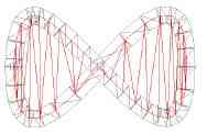
Figure 2: the tesselation of a stroked and filled path.
Stroking a general path is more difficult, since it may contain ellipse and Bezier segments, two primitives that are not directly supported by OpenGL. To rasterize Bezier curves, OpenGL provides evaluator objects which are meant to be hardware-accelerated. However, SVGL does not use evaluators to stroke paths since they can only produce a limited range of wide lines. Hence, SVGL needs to compute the stroke envelope of each path. It uses a fast forward differencing method to transform curved segments into lines [17].
SVGL iterates on each line segment, computes the rectangular envelope around it and send it to OpenGL for rendering. This computation is simple but requires several floating point computations: one hypotenuse to compute the norm of the vector normal to the line direction—less expensive than a square root — 2 divisions to normalize the vector, two multiplications of the vector coordinates by the line width to get the envelope width and 8 additions to compute the coordinates of the envelope. More shapes are added between two lines envelopes to render the join style, involving more computation for miter joins but not for round or bevel joins.
Filling Non-Convex Shapes
SVG shapes such as path, polygon and polyline may be non-convex and should be decomposed into convex shapes for OpenGL rendering. This tessellation is done by a set of utility functions provided by the GLU library.
4.2 Clipping
SVG shapes can be clipped by a clip path, an area defined with other SVG shapes. OpenGL offers three mechanisms to implement clipping: scissors, stencil buffer and depth buffer. SVGL uses either the stencil buffer or the depth buffer, depending on a compilation directive. Using the stencil buffer frees the depth buffer if we want to implement 3D extensions or out of order rendering. However, hardware supported stencil buffer is much less common than hardware supported depth buffer and since clipping is used on several common rendering cases, we offer both. In the following, we use the term clip buffer to refer to the buffer used for clipping.
The algorithm consists in drawing the clip path into the clipping buffer using a particular “clip” value, then allowing the drawing of clipped shapes only where pixels in the clip buffer has been set, and drawing the clipped shapes.
To allow recursive clip paths, the algorithm increments the clip value when drawing into the clip buffer. Drawing is only allowed for pixels with the same clip value than the maximum clip value in the clip buffer. To disable a clip path, the bounding box of the clip path is drawn and decrements the values in the clip buffer that passes the clip test. This scheme implements a kind of stack where drawing only occurs for clip values equal to the top of the stack. To pop the stack, SVGL inverts the clip test, and redisplays the clipped shapes bounding box, as it is always faster than to redisplay the shapes themselves. Since only pixels that have been pushed will pass the clip test, removal of unpushed pixels will not occur.
With the stencil buffer, setting a particular clip value consists in setting the corresponding OpenGL state variable. Thus, every shape will be drawn with the current stencil value. The clip test passes only when value in the stencil buffer equals the incoming stencil value.
With the depth buffer, SVGL renders non clipped shapes at a certain distance from the viewpoint. The clip value corresponds to the translation along the z-axis given by the multiplication with the model-view matrix. Before rendering clipped shapes, we translate the shape closer to the viewpoint. A mask disables writing pixels in the color buffer while enabling writing into the depth buffer. The clip path is then rendered using the mask and shapes that need to be clipped are then rendered with an inverted mask. Depth culling occur when incoming pixels have a different z value then pixels already drawn.
4.3 Opacity
If shapes are not opaque, their pixels have to be blended with existing ones in the color buffer. OpenGL handles transparency natively, and supports some of the alphablending operations described in [15]. However, two problems arise when dealing with transparency: selfintersection and semantics of shape transparency.
A stroke can be self-intersecting or have overlapping parts produced during by the envelope generation. If the stroke is not opaque, blending these overlapping parts produces incorrect results, as shown in figure 3.
To solve this problem, we use a clipping mechanism: when a pixel belonging to the shape is blended with the background, the clip buffer receives a value that disables forthcoming blending. This algorithm avoids expensive computations of overlapping areas. We could have used the GLU tessellation routines to analytically compute self intersections, but we have chosen to let the hardware do it at no cost for the CPU. Strategies like this one are at the heart of the techniques that benefit from hardware features.
The second problem comes from the semantic of the “opacity” attribute when applied to a group of shapes, or when applied to a shape both stroked and filled. Inside a non-opaque group, shapes must not be blended together. Only the resulting image of the group should blend with previous pixels. The group must be rendered as if there was no “opacity” value, then it must be blended into the actual scene using the opacity value (see figure 4).
This behavior implies the use of a two-pass algorithm. First, the bounding box of the group is computed using the algorithm explained below. SVGL then saves the current image in a texture, clears the bounding box area, and renders the group in the image. Finally, it composes the texture of the previous image as if it were “under” the newly created image, using the right alpha-blending operation and the opacity value. This mechanism is very different from software based renderers that allocate a memory area to render the group and compose it over the main image. Using OpenGL, rendering has to be performed in the image to fully benefit from hardware acceleration.
SVG defines three opacity attributes: “opacity”, “fillopacity”, and “stroke-opacity”. “opacity” acts as if a shape was a group of two shapes, i.e blending occurs only between the resulting image and the previous image, not between stroke and fill. In this case, the shape must be rendered using the above algorithm and blended into the actual scene. However, unnecessary computation can be avoided if stroke is not semi-transparent. In this case, using the clip buffer when drawing stroke, then forbidding drawing where stroke was rendered, and finally drawing fill will give the correct result. If “opacity” equals to 1, the basic algorithm can be applied.
if fill!=none and stroke!=none and opacity<1
if stroke_opacity=1
set OpenGL opacity to opacity
draw stroke in color and stencil buffer
set OpenGL opacity to opacity X fill_opacity
if fill recovers itself
draw fill in color and stencil buffer
else
draw fill in color buffer
get bounding box
draw in stencil buffer to pop it
else
apply two pass algorithm with stroke and fill
else
if stroke!=none
set OpenGL opacity to opacity x stroke-opacity
if OpenGL opacity<1 and stroke recovers itself
draw stroke in color and stencil buffer
get stroke bounding box
draw stroke in stencil buxffer to pop it
else
draw stroke in color buffer
if fill!=none
set OpenGL opacity to opacity x fill-opacity
if OpenGL opacity<1 and fill recovers itself
draw fill in color and stencil buffer
get fill bounding box
draw fill in stencil buffer to pop it
else
draw fill in color buffer
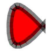
Figure 3: blended parts of a shape generate artifacts.
4.4 Text and Fonts
SVGL text rendering engine supports two well-known methods to render text strings. When character size is small enough (typically under 20), SVGL generates on the fly a texture containing a set of characters of the same font at the same size. Rendering a line of text consists in drawing quads while mapping the corresponding texture on it. To apply a particular character, SVGL changes the texture coordinates to the ones pointing to the character. The format of the font textures is one opacity value per pixel. Using an opacity value allows the use of antialiasing effects, by blending character edges with background.
As size becomes larger, font textures get larger. Texture size is limited, as well as the available textures quantity in graphical memory. SVGL handles text with large font size with vectorial fonts i.e characters described with paths. Since vectorial fonts are transformable without any artifacts, they are also used if a non-uniform scaling or a rotation has been done, typically when a text follows a path.
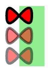
Figure 4: the same path totally opaque, with strokeopacity and fill-opacity set to .5, and with opacity set to .5.
4.5 Bounding Box Determination
Some rendering techniques described in this paper needs to determinate the bounding box of the shapes in window coordinates. Usually, the determination of the bounding box uses an analytical algorithm. To compute bounding boxes, SVGL uses the OpenGL feedback mode. Instead of rendering primitives, this mode computes and returns coordinates of primitives that would have been rendered in rendering mode.
For each basic shape, a non-transformed surrounding rectangle can be efficiently computed. The algorithm consists in traversing the graph, applying transformations and rendering for each shape its surrounding rectangle, then recovering back the information generated by the feedback OpenGL mode.
By using the feedback mode, SVGL avoids the need to duplicate OpenGL functionality, such as geometrical transformations. Hence, SVGL uses less code and is less likely to contain bugs due to minimal differences with the implementation with the OpenGL library. Furthermore, by using a single function for drawing and for computing a bounding box, we are sure that we will obtain the same results. For example, an analytical algorithm would require to handle transformations due to the traversal of an element that redefine its “viewBox” attribute, while the actual rendering process handles this behavior. Finally, imitating OpenGL rendering process would require to handle differences between the different versions of OpenGL drivers.
4.6 Viewports and Aspect Ratio
Some SVG elements define their own viewport, transforming their sub-graph to match the characteristic of the viewport. For example, <svg> elements inside an SVG document can stretch uniformly their graphics to fit it in a smaller area. Most special-purpose shared branches, such as <marker> and <symbol> , can define their own viewBox.
SVGL applies transformations on the model-view matrix before rendering the content of such an element. In particular, it applies a translation and a scale to displace and stretch the sub-graph. Additionally, it may enable a clipping area to avoid drawings external to the viewbox
4.7 Geometrical and Style Transformations
Geometrical transformations and most styling transformations of a group apply to sub-graph shapes. As OpenGL is a state-machine, a simple algorithm would be to apply both kind of transformations before traversing sub-graphs. This algorithm works for geometrical transforms, since they are compatible between SVG and OpenGL.
Applying style transforms is not as straightforward, as some style attributes have no corresponding OpenGL primitives. For example, stroke width cannot be directly handled by OpenGL, and cannot be set using an OpenGL state variable. Second, some attributes have a semantic that is not compatible with OpenGL one, such as group opacity. Finally, though set in a parent node, some attributes apply for a shape using its proper characteristics. For example, gradients may be drawn either according to absolute coordinates, in which case it can be applied at the level of a group, or it may be drawn according to each shape bounding box. In this case, SVGL deferred state changes until the traversal of each shape.
4.8 Color Gradients
SVG shapes can be filled and stroked with gradients, i.e a smooth linear or radial shade of colors. SVGL uses OpenGL trilinear color interpolation and a clip-based algorithm to implement both flavors.
A gradient is partly defined with <stop> elements that provides color and position information. Additionally, a vector defines the direction of a linear gradient. Finally, either the gradient coordinates are relative to the bounding box of the shape using it, or they are relative to the user space on use.
The algorithm first defines a clipping area defined by the shape to be filled. Since pixels outside the shape will be clipped, only the shape pixels will receive the gradient colors. If the coordinates of the gradient vector are relative to the bounding box of the shape, a rectangle surrounding the shape must be computed, as seen in figure 5. This rectangle is filled with the gradient, possibly multiple times, depending on the “spreadMethod” attribute.
For each <stop> color, a rectangular band with a stop color at each side is defined, enabling OpenGL colors interpolation from one side to the other. SVGL uses the same algorithm to fill radial gradients. An adapted gluDisk function draws the circle slices by defining at each vertex the color to interpolate.
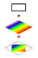
Figure 5: construction of a linear color gradient.
4.9 Filters
SVG filters apply operations onto rasterized pixels. They range from blurring to complex lighting of a shape. Filters use very different techniques to achieve their effect. For example, blurring uses convolution, while lighting and morphology employ a special-purpose algorithm.
The GL ARB imaging extension of OpenGL 1.2 allows the use of hardware-accelerated convolutions. Additionally, it provides a color matrix to transform pixels color when manipulating pixels. When available, SVGL uses the extension to implement some of the filters. If the extension is not available, or if a filter is implemented through a special-purpose algorithm, SVGL has to implement the algorithm in software. This scheme requires a part of the image to be transfered from the frame buffer to the main memory, processed and written back.
Filters apply in a certain order, given by an input/ output flow. When filters have one input each, a one pass algorithm can be used. When filters have two inputs, single input branches are rendered then saved into a texture, before being reused by the multiple inputs filters.
4.10 Picking
Interaction on SVG documents uses builtin WIMP events that triggers scripted actions. SVGL does not implement this model, since we plan to use a post-WIMP interaction model in the future. However, interaction is based on picking, no matter the model. Picking is the process of determining objects lying into a small square around the cursor position, and allows to find a particular shape that has been designated or passed-over. As shapes can be arbitrarily transformed, determining analytically the shapes a user has pointed is often difficult. OpenGL can render a scene in a “selection” mode and provide the programmer with information about the set of primitives that are included in the area of the cursor position.
SVGL uses OpenGL selection mode to implement picking. For each shape that lies into the picking area, the pick manager returns a stack corresponding to the path in the graph followed during the traversal, up to the shape. For example, a stack might resemble to this one: <svg><g><use><symbol><g><rect> Thus, a developer can easily adapt the interaction in function of the traversed SVG elements.
This algorithm has two problems. Since a stack is generated for each OpenGL shape that lies into the picking area, distinct parts resulting from tessellation are likely to generate multiple stacks though one would be sufficient. SVGL removes multiple similar stacks, as a developer is concerned by only one of them.
The second problem is that in selection mode, OpenGL does not use the stencil test. Hence, SVGL has to detect if a shape that hits the picking area is actually visible. The method consists in detecting if a clip path is drawn. If the clipping path actually hits the selection area, then any subsequent shaped clipped by this path are likely to be picked. If a regular shape in the stack is clipped, it is actually picked if the corresponding clip path has hit the selection area.
4.11 Optimizations
SVGL is implicitly optimized for geometrical and style changes, since changes can be factored out in groups of shapes. SVGL benefits from this optimization by applying changes to OpenGL state-machine when possible. OpenGL offers many other ways to optimize the rendering process. SVGL uses two mechanisms: display lists, and texture changes minimization.
Display Lists
Display lists cannot be changed once created, hence they are useful when drawings are the same across frames. Since most shapes do not change, SVGL uses display list to draw them.
Display lists do not apply only to shapes but to transformation as well. Thus, transformation due to shapes positioning or due to viewbox operations can be encapsulated into a display list. However, shared SVG elements may use their parent characteristic to be displayed. For such cases, a display list per element is not sufficient. As of this writing, SVGL does not use display lists for this kind of transformation. Only shapes drawing generates display lists used in subsequent drawings: one for stroke, and one for fill. As an example, using display lists multiplies by 25 the frame rate when displaying the tiger (figure 1.)
Reordering of Text Spans
Most readable texts use small enough font sizes to be drawn using textures. However, formatted texts have often multiple font sizes and faces, to differentiate headings and regular paragraphs. Displaying such texts using the flow of characters is inefficient, since it implies many texture swappings, where a number of swaps equal to the number of texture would be sufficient.
SVGL is able to reorder text spans inside a text to minimize the number of texture swaps. The manipulation should occur only if text spans are not translucent and do not overlap, otherwise the result will not be the correct one.
4.12 Summary of Hardware Support Used by Svgl
OpenGL hardware-accelerated functions support a number of SVGL features. Transparency implements opacity and fonts anti-aliasing. Geometrical transformations position, stretch, rotate shapes, and implements viewbox transformations. Textures are used by fonts, patterns and transparent groups. Stencil or depth buffer enables clipping, pre-rendering of semi-opaque group, and gradient filling. Color interpolation is used in gradient. Display lists accelerate static shape rendering across frames. Convolutions and the color matrix help implementing filters. Though not hardware-accelerated, feedback and selection modes respectively helps in determining bounding boxes and selection with a picking device.
5 Results And Discussion
We have compared the speed of SVGL with two other SVG engines: Batik from the Apache XML project and the Adobe SVG Plug-in. Batik is written in Java whereas the Adobe SVG Plug-in is written in C or C++. We have compared the time required to render three different scenes:
- an illustration representing a tiger, representative of graphically rich scenes;
- a textual page with several font changes, representative of rich textual documents, and
- a dense starfield display using transparency, representative of demanding visualization applications.
1. a 700MHz Pentium III processor using an ATI Rage Mobility M1 on a laptop computer running Windows 2000. The GPU does not accelerate transformations and has no stencil buffer.
2. a 1GHz Pentium III processor using an NVidia GeForce2GTS running RedHat Linux 7.0. The GPU has transformation acceleration and a stencil buffer.
5.1 Discussion
The results are summarized on the table 1 and show that SVGL is the fastest viewer in all tests. On configuration 1, SVGL is 3 times faster than Batik for the tiger benchmark and 10 times faster on configuration 2. This results highlights the benefit SVGL gains with hardware acceleration. For the same benchmark, SVGL is 3 times faster than Adobe SVG viewer on configuration 1.
For the text benchmark, hardware texture mapping for fonts is up to 100 times faster than Batik and 55 times faster than Adobe SVG Viewer. Adobe SVG viewer and Batik are probably able to avoid displaying clipped characters, explaining the improvement when zooming in whereas SVGL exhibits no difference between the min and max values. For this test, Batik is much slower on a Linux/X11 platform than on Windows because of issues with font rendering implementation.
For the starfield benchmark, SVGL is 2 times faster than Batik at worst and 10 times when all the starfield shapes are visible. Compared to Adobe SVG viewer, results are closer. However, this benchmark continuously display 10,000 translucent rectangles of different colors and sizes. SVGL cannot rely on display lists to avoid resending the same data because starfield configurations can change at each frame. The rendering speed is probably limited by the transfer speed of the bus between the CPU and the GPU. Using a display list improves the performance by a factor of 17.
6 Conclusion and Future Work
In this paper, we have described SVGL, a toolkit that displays visually rich SVG documents using hardwareaccelerated graphical functions from the OpenGL library. The main objective of SVGL is to offload graphical processing complexity of the CPU to the GPU, and benefit from the GPU power for graphical computations. We have described how some SVG primitives are turned into OpenGL ones, and showed how SVGL applies optimizations on the scene graph. We have measured performances with three typical examples against other SVG viewers, and showed that SVGL is always faster, sometimes by a factor of 10 or more.
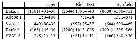
Table 1: Time in millisecond required to draw images for three SVG Viewers. Maximum and minimum time are given for all the viewers. Startup time in parentheses is only available for Batik and SVGL.
We are currently working on adding implicit and explicit optimizations in SVGL. Explicit optimizations include scene graph simplification, elimination of invisible primitives (culling) or space partitioning of primitives for faster viewport culling. Dynamic optimizations include automatic simplification of shapes when the frame rate becomes inadequate and the use of “level of details”. We are also adding semantic zooming using a simple extension of the <switch> SVG element. Finally, we plan to add multi-layering as described in [6].
To use SVGL in interactive applications, we are currently designing a higher-level API that will provide common interaction techniques such as tool-glasses relying on SVGL features. When available, this toolkit will provide the speed and graphic quality needed by designers to develop the next generation of user interfaces.
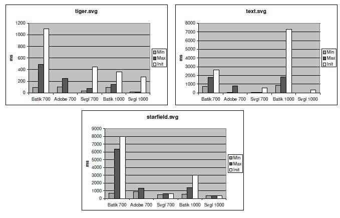
Figure 6: Time required to render the 3 scenes using Batik, the Adobe SVG Plug-in and SVGL using two different hardware configurations: a 700Mhz P3, and a 1Ghz P3+GeForce2 GTS.
7 Acknowledgements
This work has been inspired by several meetings of the French “ALF” working group of the I3 CNRS Research Group (see http://www.cict.fr/alf). Thanks to all participants collectively.
References
[1] Michel Beaudouin-Lafon and Henry Michael Lassen. The architecture and implementation of CPN2000, a post-WIMP graphical application. In Proceedings of the 13th Annual Symposium on User Interface Software and Technology (UIST-00), pages 181–190, N.Y., November 5–8 2000. ACM Press.
[2] Ben Bederson and Jon Meyer. Implementing a zooming User Interface: experience building
[3] Benjamin B. Bederson and James D. Hollan. Pad++: A zooming graphical interface for exploring alternate interface physics. In Proceedings of the ACM Symposium on User Interface Software and Technology, Visualization I, pages 17–26, 1994.
[4] Benjamin B. Bederson, Jon Meyer, and Lance Good. Jazz: an extensible zoomable user interface graphics toolkit in java. In Proceedings of the 13th Annual Symposium on User Interface Software and Technology (UIST-00), pages 171–180, N.Y., November 5–8 2000. ACM Press.
[5] Eric A. Bier, Maureen C. Stone, Ken Pier, William Buxton, and Tony DeRose. Toolglass and Magic Lenses: The see-through interface. In James T. Kajiya, editor, Computer Graphics (SIGGRAPH ’93 Proceedings), volume 27, pages 73–80, August 1993.
[6] Jean-Daniel Fekete and Michel Beaudouin-Lafon. Using the multi-layer model for building interactive graphical applications. In Proceedings of the ACM Symposium on User Interface Software and Technology, Papers: Tools, pages 109–118, 1996.
[7] Paula Ferguson and David Brennan. Motif Reference Manual, volume 6B. O’Reilly & Associates, Inc., 981 Chestnut Street, Newton, MA 02164, USA, June 1993.
[8] J. D. Foley, A. van Dam, Steven K. Feiner, and John F. Hughes. Fundamentals of Interactive Computer Graphics. Addison-Wesley Publishing Company, second edition, 1990.
[9] Antonin Guttman. R-trees: a dynamic index structure for spatial searching. SIGMOD Record (ACM Special Interest Group on Management of Data), 14(2):47–57, 1984.
[10] Gordon Kurtenbach, George W. Fitzmaurice, Russell N. Owen, and Thomas Baudel. The hotbox: Efficient access to a large number of menu-items. In Proceedings of ACM CHI 99 Conference on Human Factors in Computing Systems, volume 1, pages 231–237, 1999.
[11] Mark Linton and Chuck Price. Building distributed user interfaces with Fresco. The X Resource, 5(1):77–87, January 1993.
[12] Mark A. Linton, John M. Vissides, and Paul R. Calder. Composing user interfaces with interviews. IEEE Computer, 22(2):8–22, February 1989.
[13] Open Inventor Architecture Group. Open Inventor C++ Reference Manual: The Official Reference Document for Open Systems. Addison-Wesley, Reading, MA, USA, 1994.
[14] Stuart Pook, Eric Lecolinet, Guy Vaysseix, and Emmanuel Barillot. Context and interaction in zoomable user interfaces. In Proceedings of AVI 2000, pages 227–231 & 317. AVI 2000, Palermo, Italy, ACM Press, May 2000.
[15] Thomas Porter and Tom Duff. Compositing digital images. In Hank Christiansen, editor, Computer Graphics (SIGGRAPH ’84 Proceedings), volume 18, pages 253–259, July 1984.
[16] Jeff Prosise. Programming Windows With MFC. Microsoft Corporation, One Microsoft Way, Redmond, WA 98052-6399, USA, 2nd edition, May 1999.
[17] Thierry Pudet. Real Time Fitting of Hand-Sketched Pressure Brushstrokes. In Eurographics’94. Proceedings of the European Computer Graphics Conference and Exhibition, Amsterdam, Netherlands, 1994. North-Holland.
[18] Henry Sowizral, Kevin Rushforth, and Michael Deering. The Java 3D API Specification, Second Edition. Addison-Wesley, Reading, MA, USA, 2000.
[19] Andries van Dam. The human connection: Post- WIMP user interfaces. Communications of the ACM, 40(2):63–67, February 1997.
[20] Mason Woo, Jackie Neider, Tom Davis, and Dave Shreiner. The OpenGL Programming Guide. Addison- Wesley, Reading, MA, USA, 3rd edition, August 1999.