DRILLING FLUID CLEANING SYSTEMS: MAXIMIZING EFFICIENCY


Course: This article was published in the NK Rosneft Scientific and Technical Newsletter (Nauchno-tekhnicheskiy Vestnik OAO “NK “Rosneft”, No.3, 2010, pp. 14-17; ISSN 2074-2339) and won the 3-rd prize in the 2010 competition for the best publication in the newsletter. â 2010 ã.
   Well construction technology that is currently used not only causes surface disruptions, but also affects physical and chemical conditions at depth during the penetration of reservoir beds while drilling. Substances contaminating the environment during well drilling include various chemical reagents used for the preparation of drilling fluids, and cleaning systems are used to improve the quality of these fluids.
   Cleaning units are meant for low-waste drilling technology and are included into the circulation systems of all types of drilling rigs. Circulation system equipment ensures:
    Circulation system equipment ensures:
  » rough cleaning of drilling fluids on vibrating screens;
  » solution processing on sand- and silt- separators with separation of low humidity slime (pulp);
  » centrifuge separation of two non-soluble mixed fluids of different density;
  » multiple usage of drilling fluid and extraction of excess colloidal phase, as well as regeneration of barytes upon well completion;
  » processing of surplus drilling fluid with separation into recyclable water and low humidity slime;
  » degassing of drilling fluids.
   Using complete solids control units provides a 1.5 fold decrease in drilling waste and 15-20% reduction in the consumption of chemical reagents. During closed-loop drilling, the solids control unit produces drilling waste which is suitable for transporting in containers or platform vehicles.

   This waste is easily neutralized using existing technologies at minimum cost. Well cleaned drilling fluids significantly reduce the risks of formation damage, blockages and increase the repair interval for drilling equipment.

   ÑComparative analysis of cleaning systems with a full and reduced instrument set as seen on BU3000EUK-1M pressure piping.
   Currently, there is a four-stage cleaning system - vibrating screen/sand separator/silt separator & centrifuge - where at every stage the drilling fluid can be cleaned to a certain grain size. Fig.1 shows the flowchart for a cleaning system with a reduced instrument set, which includes two vibrating screens, one paired sand separator, a silt separator and two centrifuges


Fig. 1. Flowchart of reduced solids control system (two vibrating screens) as on BU 3000 EUK-1M: 1 – sludge pump; 2 – vibrating screen; 3 – sand separator (paired); 4 – silt separator; 5 – auger conveyor; 6 – centrifuge; 7 – axial flow pump; 8 – degassing unit.
   Drilling fluid from the wellhead goes through a mud return flowline or ditch to the vibrating screens, where it undergoes rough cleaning to grain size 143 microns. Then, using sludge pumps, the drilling fluid goes to the sand separator, where it’s refined to 12 microns in size. After this, using an axial flow pump, the drilling fluid is sent to the centrifuge, cleaned to 2 microns in size and finally the purified fluid is taken to the well with mud pumps. Discharge of this solution into any active tank is admitted, and tank usage order may also be altered.

   This flowchart does not allow for the drilling fluid to be purified to the necessary state, mainly because only two vibrating screens are used.

   The pulp from the assembled sand and silt separators dropping on screens with wide screen size (800-120 micron) will fall through into the tanks of the rough-cleaning circulation system (RCCS), which will cause contamination of the tank and increase the density of the drilling mud. Thereafter, the sand separator won’t be able to handle the solution of such density, and the larger part of unprocessed drilling fluid will get into the active tanks. If the vibrating screens equipped with sand and silt separators have smaller screens installed (120-55 micron screen size), then the second vibrating screen won’t be able to handle the handle the entire volume of all the drilling solution exiting the well, which will lead to losses and the screen area won’t be sufficient for quality operation. Also, if the silt separator is not used and the solution is fed directly from sand separators to the centrifuge, this can lead to its breakdown. If the centrifuge is not used either, the uncleaned solution will get into drilling pumps, which will cause the following problems:
  » increased use of spare parts of rapidly wearing drilling pumps;
  » faster wear of manifold, sludge pumps & downhole motors;
  » increased risk of drilling tool freezing.
   All of this leads to drill rig downtime, decreased mechanical drilling speed and financial losses.

   At the present time, the Nefteyugansk branch of LLC “RNBureniye” has switched over to using the cleaning system with full instrument set (fig. 2). Differing from the system reviewed above, it has an added shaker-desander unit(SDU), consisting of drying vibrating screen, where sand and silt separators are installed.


Fig. 2. Flowchart of full solids control system as on BU 3000 EUK-1M: 1 – sludge pump; 2 – vibrating screen; 3 – shaker-desander unit (SDU); 4 – sand separator (paired); 5 – back-up sand separator; 6 – silt separator; 7 – auger conveyor; 8 – centrifuge; 9 – auger-type pump; 10 – degassing unit
   When using full instrument cleaning set, the drilling solution takes a similar route to that shown in fig. 1. The second system is more preferable mainly due to the third vibrating screen. The SDU has smaller screens with 120 to 55 micron screen size, thus drilling waste from the sand and silt separators drops onto these screens and does not fall through into RCCS tanks, but is purified to 55 micron grain size.
   The hard phase (residue) which can’t be cleaned, is discharged into the auger conveyor.

   All of this allows an increase in the quality of cleaning while minimizing the loss of the drilling fluid. One other advantage of this system is that the second linear vibrating screen has a back-up sand separator installed, which, in the case of the paired SDU sand separator going down, allows you to switch the operation to two vibrating screens and a sand separator, without stalling the drilling. However, even when full instrument kit cleaning system is used, errors are possible that can render all the cleaning efforts null and cause a rapid breakdown of the equipment. Primarily, these could be:
  » improper pressure piping: wrong selection of pumps, diameters and sections of the pipes;
  » incompliance to the operation and maintenance chart (incorrect selection of vibrating screen baskets and sand and silt separator headers, not following the proper order of cleaning system units operation (starting the silt separator);
  » errors while adjusting cleaning system equipment units (vibrating screens, centrifuges and feeding pumps).
   The article shows a comparative economical analysis of two cleaning system arrangements. Fig. 3 shows expenses for spare parts, tools and accessories (SPTA). It is clear that with the rational usage of full solids control system, expenses for SPTA are significantly reduced.


Fig. 3. Annual expenses for SPTA on drilling equipment per one drilling rig.
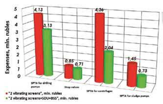
   The comparative table shows all costs and expenses for one calendar year per one drilling rig, as well as expenses for one incident mitigation, related to using low quality drilling fluid. As per statistical data of NB LLC “RN-Bureniye” for 2007-2009, using the full solids control system shows at least one less incident per year than that of thereduced set system.


Conclusion

   Disadvantages of reduced solids control systems(two vibrating screens) have been revealed. Certain problems, which if avoided could also improve the efficiency of drilling fluid cleaning and processing have also been identified. The economical analysis shows that the rational usage of the full solids control system accounts for 6.81 million rubles in savings per drilling rig, which for all 11 crews of NB LLC “RN-Bureniye” totals up to 74.91 million rubles.

List of literature used


  1. Bulatov A.I., Makarenko P.P., Proselkov Y.M. Drilling washing and backfilling fluids: Textbook for universities. Moscow, Nedra, 1999. – 424 p
  2. Drilling equipment/V.F. Abubakirov, Y.G. Burimov, A.N.Gnoyevykh etc. Reference guide in 2 vol. – Moscow, Nedra, 2003. – 763 p.