
Abstract
Content
- Introduction
- 1. Theme urgency
- 2. Goal and tasks of the research
- 3. The choice of resistors for neutral grounding
- Conclusion
- References
Introduction
To date, the conditions of constant deterioration of the technical state of distribution networks due to the lack of necessary funds for the timely replacement and quality repairs of damaged electrical equipment all the more acute becomes the problem of maintaining sufficient for the required level of reliability of power supply systems of electric power consumers. Average duration of operation of most of the main electrical significantly higher than standard terms of service. Distribution networks are usually long-term extension and are working under very difficult conditions of pollution, humidity, frequent dynamic and thermal loads. All these factors lead to an increase in damage to electrical networks due to various defects, including developing under the influence of the operating voltage [1].
1. Theme urgency
The greatest danger is posed by arc voltage, the presence of which may cause significant overvoltage that lead to the breakdown of the insulation of high voltage electric motors, circuit between phases, fires, and others. In addition, for the o.n. power plant is characterized by a relatively low level of capacitive earth fault currents, which in many modes of operation of the unit leads to a lack of sensitivity of single-phase protection against earth fault (PEF) [2].
In order to improve the reliability of networks 6–10 kV, conducted an intensive search for ways to address two main questions:
- increasing the sensitivity and selectivity of the relay protection of single phase earth fault;
- b) surge suppressor and prevent ferroresonance processes that can cause damage to multi–network, reducing the lifetime of isolation and failure of electrical equipment [3,4].
One way to address these issues now is resistive (high or low voltage) neutrals grounded networks by connecting transformers (CT) [5].
2. Goal and tasks of the research
Consider the advantages and disadvantages of networks with resistive–grounded. Analyze the way to improve the reliability of networks with isolated neutral during the closure phase to earth with an integrated low–voltage neutral grounding device and automatically bypass faulted phase, which deals with the problem of increasing the sensitivity of the relay protection, surge suppression and long arc-fault exception.
Main tasks of the research:
- To evaluate the effectiveness of low–voltage neutral grounding resistor network 6 kV auxiliary power on the results of mathematical modeling and experiments on a physical model
- Perform simulation of single phase earth fault using the proposed method and show its advantages.
- Develop a device implementing the proposed method, the scheme of its protection and management, which exclude the long arcing ground fault and do not require high–temperature resistant resistor.
Research object: the processes in networks with isolated neutral.
Research subject: the transients in the PEF, and ways to minimize their impact on the reliability of networks.
3. The choice of resistors for neutral grounding
Electric network voltage of 6–35kV are widespread and relate to the network, working with isolated neutral. To improve the reliability of these networks, depending on the voltage, the capacitive earth fault currents greater than 10–30 A is applied through the neutral grounding reactance to compensate for capacitive currents [6]. For networks with currents less than the specified closing, recently used the network through the neutral grounding resistance.
The network's own needs 6 kW of power and atomic power plants require a neutral grounding resistor network via the low impedance of 100 ohms, which is connected to the transformer neutral special TSNZ–63–10 capacity of 63 kVA. Installation of the resistor increases the ground –fault currents, which provides selective operation of relay protection, which acts to turn off the damaged connection [7]. However, in order to reduce the thermal action of the arc and increase the heat resistance of the resistor, in [8] recommend the use of high value resistors 1000–2000 ohms. On the positive side setting resistors are reduced to the level of surge (2.2 – 2.5) Uf, prevention of occurrence of ferroresonance processes and improved clarity of the protection relay. Currently, Novosibirsk company "TNG Bolide" resistors are designed and manufactured from a material "EHM" (electrically conductive composite material – ceramics with conductive additives), which have high thermal stability and can be long-term (up to 6 h) to remain in work with single –phase ground faults. However, the disadvantage of the resistors is the high cost, the complexity of the design, the complexity of installation and commissioning. In connection with the foregoing, it is urgent to further improve the method of increasing the active component of fault current to earth, does not require the installation of high voltage resistors.
There are two ways to connect a resistor:
- a resistor connected to the neutral of the transformer windings higher voltage (Fig. 1);
- connecting a resistor in open delta winding of the transformer low voltage (Fig. 2).
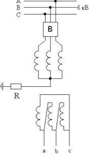
Fig. 1. Scheme resistor connected to the neutral voltage transformer windings higher
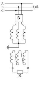
Fig. 2. The scheme of connecting the resistor in ferro resonance winding low voltage transformer
By the method described in [9], were obtained and the calculated waveforms of arc extinction for different values of the grounding resistor is included on the diagrams Figure 1, Figure 2. Calculated waveforms are shown in Figures 3 and 4, which shows the zero-sequence voltage and the faulted phase, as well as currents in the place of an earth fault.

Fig. 3. Oscillogram of currents and voltages in the event and turned off at PEF neoptymalnoy value resistor

Fig. 4. Oscillogram of currents and voltages in the event and turned off at PEF optimal value of the resistor
As seen in Figure 3, with a high–value resistor 100 k in the neutral of the transformer or its equivalent resistor 3.9 ohms in the circuit open–loop triangle residual voltage decays in a time of 0.2 s, which when re–PEF can cause a significant overvoltage and ferroresonance process.
When you turn on the same resistor value of 1000 ohms, respectively, for a scheme of Figure 1 and 39 ohms for the circuit voltage decay of Figure 2 shows the zero–sequence with the disappearance of PTG (Fig. 4) occurs at the desired time is 0.01 s.
As a result of the foregoing, it can be concluded about the feasibility of using low–voltage neutral grounding resistor network. This method requires less with the same technical efficiency.
Conclusion
In planned unit development of the proposed method, the scheme of its protection and management, which exclude the long arc earth fault and do not require high-temperature resistant resistor. According to the results of calculations using mathematical models and operating experience elements will be concluded whether the proposed device limitations and increasing overvoltage protection relay chuvstvitedlnosti PEF in networks 6-10 kV effective.
References
- Терещенко А.В. Эксплуатация ОПН в сетях 6–35 кВ ОАО «Крымэнерго»
- Сивокобыленко В.Ф., Лебедев В.К., Сердюков Р.П. Ограничение перенапряжений и повышение чувствительности защит от замыкания фазы на землю в сети собственных нужд 6 кВ электростанций. – Сб. научных трудов ДонГТУ. Серия: Электротехника и энергетика.
- О необходимости изменений режимов нейтрали в сетях 3–35кВ / [Стогний Б.С., Масляник В.В., Назаров В.В. и др.] // Энергетика и Электрификация. – 2001. – №4. – С. 27–29.
- О регламентации вариантов заземления нейтрали электрических сетей 3–35 кВ / [Стогний Б.С., Масляник В.В., Назаров В.В. и др.] // Энергетика и Электрификация. – 2001. – №11. – С. 28–31.
- Лебедев В.К., Алесич Н.С. Повышение эффективности функционирования сетей 6–10 кВ в режимах замыкания на землю – Тезисы научно–технической конференции «Электротехнические и электромеханические системы». – Донецк, 2012.
- Правила устройства электроустановок. – М.: Энергоатомиздат, 1985. – 640с.
- Циркуляр Ц-01-88. О повышении надежности сетей 6 кВ собственных нужд энергоблоков АЭС. – М., 1988. –7с.
- Евдокунин Г.А., Гудилин С.В., Корепанов А.А. Выбор способа заземления нейтрали в сетях 6-10 кВ. – Электричество, 1998, №12. –С. 8–22.
- Сивокобыленко В.Ф., Лебедев В.К. Переходные процессы в системах электроснабжения собственных нужд электростанций (учебное пособие). РВА ДонНТУ, Донецк – 2002, 136с.
- Повышение надежности работы карьерных сетей при однофазных замыканиях на землю / [Сивокобыленко В.Ф., Лебедев В.К., Ковязин А.В., Сердюков Р.П. и др.] // Сб. научн. тр. ДонНТУ. Серия: «Электротехника и энергетика». – Вып. 9(158). – Донецк: ДонНТУ, 2009. – С. 211–220.