Abstact
Introduction
1. Theme urgency
2. The purpose and research problems
3. The review of researches and workings out
4. Calculation air-lift device
4.1. Definition of account characteristics air-lift
4.2. Calculation of the account characteristic air-lift
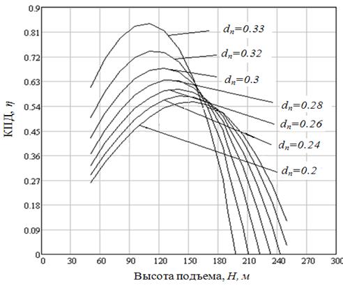
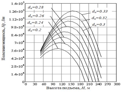
4.3. Influence of diameter of a submitting pipe on power inputs at work air-lift
Conclusions
The list of sources
1. Theme urgency
2. The purpose and research problems
3. The review of researches and workings out
4. Calculation air-lift device
4.1. Definition of account characteristics air-lift
4.2. Calculation of the account characteristic air-lift
4.3. Influence of diameter of a submitting pipe on power inputs at work air-lift
Conclusions
The list of sources
In Ukraine 47,3 thousand
industrial enterprises, from them 37,6 thousand small is. At18,8 % of
all occupied population work and is made production and services for
more than 70 подотраслей the industries.
Industrial production of Ukraine provides more than third of total amount of a total internal product, almost 50 % of the goods and services, and also 80 % of export production.
The industrial enterprises are the basic elementsof the vital spheres of the state: economic - basis of formation of cost; budgetary - filling sources; territorial - градообразователи; scientific and educational - development engines, consumers and sources of knowledge; social - places of realisation of human possibilities and maintenance with existence means; tax - sources of receipts; in financial - animators of money [1].
Coal industry of Ukraine is presented mainly by the enterprises DonetskLvovsko-Volynsk coal and Dneprovsky буроугольного pool. A basis for coal of Ukraine still there is Donbass.
Coal extract in Donetsk area. The coal industry is one of the largest branches of a national economyof Ukraine. The coal share makes not less than 94-96 % in total amount of consumed own energy carriers of the country. Maintenance necessary and enough of extracted coal is a guarantee of power independence of the state.
At the present stage of development of the industry the important role is occupied with hydrotransport in the mining industry, agriculture.
The important role in hydrotransport occupies air-lift hydrolifting.Improvement of their parametres and characteristics is very important.
The big contribution to
research эрлифтных installations was brought by scientists: Ignatov A.,
Kozyrjatsky L. Н, Kononenko A. P, Gejer V. G, Alexeys V.V., Alfyorov M.
JA, Antons I. К, Logvinov N. G, Uskov Е. В, Zelinsky V. M, Mihajlov V.
I, Лезгинцев of M.
эрлифтной installations were engaged in questions on work and start-up
such organisations: Donetsk national technical university, Sumy the
state university, the East Ukrainian national university of a name of
Vladimir Dalja, the Moscow college of mines.
The made analysis of the literature shows, that for calculation эрлифтных installations there is a set of techniques, i.e. a uniform technique not существет, and the majority of them are not adapted for the COMPUTER. In the majority of design procedures the big attention is given to the analysis of the losses influencing for work эрлифта. Consideration of influence of dynamic relative immersing will allow to raise accuracy of calculations. The substantiation of rational parametres эрлифта is important, and also possibility them to define by means of the COMPUTER. Therefore working out of a technique and its further perfection are actual.
The made analysis of the literature shows, that for calculation эрлифтных installations there is a set of techniques, i.e. a uniform technique not существет, and the majority of them are not adapted for the COMPUTER. In the majority of design procedures the big attention is given to the analysis of the losses influencing for work эрлифта. Consideration of influence of dynamic relative immersing will allow to raise accuracy of calculations. The substantiation of rational parametres эрлифта is important, and also possibility them to define by means of the COMPUTER. Therefore working out of a technique and its further perfection are actual.
The work purpose is
definition of rational parametres and design procedure working out
air-lift device .
For achievement of the specified purpose following problems are put:
- The literature analysis on the given question;
- Drawing up of mathematical model air-lift device;
- Construction of account characteristics эрлифта at the constant expense of compressed air;
- Research of power inputs.
For achievement of the specified purpose following problems are put:
- The literature analysis on the given question;
- Drawing up of mathematical model air-lift device;
- Construction of account characteristics эрлифта at the constant expense of compressed air;
- Research of power inputs.
In sources the basic
schemes эрлифтных installations, their analysis are shown, the basic
dependences are resulted, key parametres for calculation air-lift are
given [12, 27].
Some existing devices air-lift device are resulted. Theory questions эрлифтов with consideration of dependences of their productivity are taken up. The scope эрлифтных installations is shown. The calculation example air-lift is resulted at the constant expense of compressed air [27].
In a source descriptions and the analysis of designs, for mining operations from a bottom of reservoirs air-lift device are stated; bases of the theory of calculation air-lift device are stated, the basic characteristics air-lifts and areas of their application for various conditions of operation are resulted; recommendations for choice optimum parametres and to calculation are given [22, 26].
In a source descriptions and the analysis of designs, применямых for mining operations from a bottom of reservoirs air-lift device are stated; bases of the theory of calculation air-lift device are stated, the basic characteristics air-lifts and areas of their application for various conditions of operation are resulted; recommendations for choice optimum parametres and to calculation are given [22].
The designing technique эрлифтных installations is resulted: the sequence of designing, a choice of parametres for designing is defined. Descriptions, equipment characteristics air-lift device are offered. The calculation method air-lift is offered [23].
Questions on application air-lift on deep-water reservoirs are considered, ways of improvement of a design air-lift for their application are offered at mining operations. Calculation is offered, to the recommendation about calculation of constructive knots air-lift [5].
In the book researches on application air-lift on reservoirs of the big depth for the purpose of overall performance increase эрлифта are shown and analysed. Experimental dependences which reflect work эрлифта in the big depths are resulted, and also at work with a firm material [11].
In the book researches эрлифта are described, the designing and calculation methodology air-lift for its work on the big depths is offered [2, 3].
In work questions of modelling of working process эрлифта by means of the COMPUTER are considered, questions барботажного a mode air-lift are taken up and the mathematical model of process барботажа is offered, the specified calculations of parametres are carried out, dependences of account characteristics air-lift are thus shown [29].
Classification air-lifts, liquids used for transportation and hydromixes in the mining industry is offered [30].
With national economy
growth the requirement for resources increases. It is connected by that
with increase in capacities of the enterprises or input of the new
enterprises in action power resources, such as coal are required that
is in turn connected with increase in extraction of the last.
Coal mining increase – a base direction of development of a power complex of our country as coal stocks in Ukraine big enough and them are expedient for developing. For mineral extraction last years the majority of mines leaves on the big depths that involves a problem of fast and qualitative water outflow. Important value is represented by a problem of clearing of mine capacities such as зумпфов from a firm material. With a pulp all pumps, especially from the big depth can pump out a such liquid not.
It conducts all to considerable capital expenses for purchase of the new and expensive equipment, its service and repair. The cheapest and simple means for the decision of the given problems is application air-lift device.
Air-lift installations are one of the most simple on a design, are simple in management, can work on the big depths, work with a firm material. In this connection it is possible to tell, that air-lift adequately competes to others water device. The scheme air-lift is shown in drawing 2.1.

1
– an air separator; 2 – a submitting pipe; 3 – an air
pipe; 4 – the amalgamator
.
Fig. 4.1.1 Scheme air-lift
(animation: 7 frames; 15 repetitions; 76.8 kb.)
(animation: 7 frames; 15 repetitions; 76.8 kb.)
Productivity air-lift is
defined by empirical dependence:
 , (4.1.1)
Where С
и dn –
accordingly factor of giving (productivity) and diameter of an
elevating pipe air-lift device.
Volume productivity
эair-lift essentially decreases with increase in density of a
transported pulp, and mass productivity is less subject to these
changes.
In this connection at definition of operational parametres air-lift dependence is used:
In this connection at definition of operational parametres air-lift dependence is used:
 , (4.1.2)
Where Gn –
mass productivity air-lift, t/s.
 -
Relative immersing of the amalgamator:
-
Relative immersing of the amalgamator:
-
Relative immersing of the amalgamator: , (4.1.3)
Where h -
depth of immersing of the amalgamator, m;
H - height of lifting of a liquid over its level in capacities, m.
H - height of lifting of a liquid over its level in capacities, m.
Superfluous pressure in the
amalgamator air-lift at operating conditions is defined by dependence:
 , (4.1.4)
Where  -
pulp density in the bringing pipeline taking into account sliding of
firm particles concerning a liquid phase, kg/m3;
-
pulp density in the bringing pipeline taking into account sliding of
firm particles concerning a liquid phase, kg/m3;
 -
a hydraulic bias of a submitting pipe at movement in it only liquids.
-
a hydraulic bias of a submitting pipe at movement in it only liquids.
-
pulp density in the bringing pipeline taking into account sliding of
firm particles concerning a liquid phase, kg/m3; -
a hydraulic bias of a submitting pipe at movement in it only liquids.Speed of relative sliding
of firm particles:
, (4.1.5)
Where  -
speed of the constrained falling of single fractions in the conditions
of a si
-
speed of the constrained falling of single fractions in the conditions
of a si ngle-phase
stream, m/s.
ngle-phase
stream, m/s.
-
speed of the constrained falling of single fractions in the conditions
of a single-phase
stream, m/s. , (4.1.6)
Where  -
factor of resistance to movement of a firm body.
-
factor of resistance to movement of a firm body.
After transformations we will receive:
-
factor of resistance to movement of a firm body.After transformations we will receive:
 . (4.1.7)
Or
 , (4.1.8)
 From (4.1.8) relative
immersing will look like: 
 . (4.1.9)
Having substituted (4.1.9)
and in (4.1.4), we will receive:
 , (4.1.10)
Where  -
speed of movement of a liquid, m/s;
-
speed of movement of a liquid, m/s;
Where
-
speed of movement of a liquid, m/s;Where
 .
.Then expression for
pressure definition in the amalgamator will become:

 . (4.1.11)
Considering, that the
hydraulic bias is defined, 
 ,
,
,  , (4.1.12)
Where  .
.
Having executed
corresponding transformations it is had:
 , (4.1.13)
From (4.1.13) follows, that:
 , (4.1.14)
Solving the equation
(4.1.14) it is possible to calculate Gn for various, Gn  ,that
allows to investigate influence of these factors on parametres air-lift
and to define their optimum values from the economic point of view.
,that
allows to investigate influence of these factors on parametres air-lift
and to define their optimum values from the economic point of view.
The expense of air led to normal conditions, is defined on dependence:
,that
allows to investigate influence of these factors on parametres air-lift
and to define their optimum values from the economic point of view.The expense of air led to normal conditions, is defined on dependence:
 , (4.1.15)
Where q –
the specific expense of air.
 , (4.1.16)
Where  -
dynamic height of lifting, m;
-
dynamic height of lifting, m;
 -
Isothermal EFFICIENCY air-lift;
-
Isothermal EFFICIENCY air-lift;
 -
Atmospheric pressure, Pas.
-
Atmospheric pressure, Pas.
-
dynamic height of lifting, m; -
Isothermal EFFICIENCY air-lift; -
Atmospheric pressure, Pas. . (4.1.17)
 ;
; =2500
kg/m3;
=2500
kg/m3; =0,021;
 =0,2
м;
=0,2
м; ;
; =0,0526.
 ,
(4.3.2)
,
(4.3.2) , (4.3.3)