
Abstract
Contents
- Introduction
- 1. Relevance of the topic
- 2. Research Objectives, expected results
- Conclusion
- References
Introduction
Modern trends of process automation in enterprises, potentially hazardous on the explosion of gases and dusts, including coal mines, lead to the need for explosion-proof electrical equipment of digital control and protection devices, that allows to carry out a full monitoring of all functions, as well as remote control and change parameters. Output circuits of sensors and specify the units located outside the explosion-proof shell, it is advisable to do intrinsically safe, which significantly reduces their overall dimensions and allows serial devices for general use.
Scope of use of intrinsically safe electrical equipment includes signaling, communications, lighting, including the battery lights, control systems and process control. The use of such equipment increases the overall security of mining operations, promotes the growth of labor productivity and reducing economic costs.
1. Relevance of the topic
To expand the scope of intrinsically safe electrical equipment it’s necessary to solve the problem of increasing the objectivity of methods to assess intrinsic electrical and reduce labor intensity of its development through the creation of new tubeless methods to assess intrinsic circuits and improve the test chamber.
Intelligent temperature sensors, pressure, flow, and hubs and controllers of top level sufficiently powerful intrinsically needs safe power supply. The optimal level of stress for them is 12 V, in some cases (for the remote or power users) - 24V and rated current up to 5 A at a voltage of 12 V and 3 A at a voltage of 24V. In order to implement these options require fundamentally new approaches to construction of intrinsically safe power supply [1].
2. Research Objectives, expected results
According to the examination number 1843-2010 on 15.3.2010, the power supply for intrinsically safe 24 V (IAS-24) approved intrinsically safe parameters for 3 A and 0.3 A.
For the FPI-24-3:
- voltage U0, В not more than 25;
- amperage I0, mA not more than 3300;
- inductance L0, mH not more than 0,05;
- capacity C0, uF not more than 10 [2].
Production doesn’t have enough of these parameters due to the fact that the creation of new sources associated with large financial and material costs, the most practical way out of this situation is the calculation settings for current and future intrinsically safe parameters.
The main objectives of work::
- Calculate the current for different settings of which the maximum possible value of inductance and capacitance can be connected, based on this selected cables;
- Conduct a study of the source in an inductive circuit;
- Meeting the challenges.
To implement the objectives of DART study in the program Micro-Cap, which is calculated by using the options, there is no need to use the graphs of allowed values, which greatly reduces errors and increases the scope of "smart" devices of intrinsic safety.
Researches are conducted by the example of switching the active-inductive load such as an intrinsically safe power supply FPI-24-3 (nominal output voltage of 24 V, the power of the nominal output current 3 A) Ex Ib according to GOST 12.2.020-76 performed on the combined scheme (Figure. 3): with the current cut-off and disconnect from the derivative of the current load. IPI-24-3 consists of two functional units: the converter voltage 127 ...220 V DC voltage 12 V or 24 V and spark protection barrier.
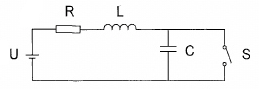
Figure 1 - Typical circuit
Currently, the implementation of this task is possible with the help of "smart" Intrinsic barriers, which feature is the presence of additional features aimed at: diagnosis and sensor lines, control performance major barrier blocks; analysis of the values in terms of intrinsic safety, adapting to changes in the parameters connected equipment. These features increase the reliability in the production of explosive devices, reduced human error. The drawback is its setup to use the graphs, regulated by GOST, in the circuit with a linear constraint.
Spark protection barrier consists of two power switches independently controlled, providing redundancy, the shunt to measure the strength of the source and the load current control circuit. Performance guarantee schemes limit the current in case of short circuit during the 2 ... 3 ms. When switching the load circuit power supply is almost completely dissipated in the resistances of the power key and does not stand out in an electric discharge. By analyzing the input signals, the controller calculates the thermal load capacity of the power key and disables them as necessary during breaks.
The calculated barrier spark protection circuit diagram is shown in Figure 1. Chain overlap and service functions of the microcontroller are not shown because they are not switching loads are involved. In the scheme are the main V1 (24) and the auxiliary voltage sources V2 and V3 (5) to supply chain security. Transistor switch X3 on the fieldeffect transistor MOSFET-IRL205_IR represented correctly SPICE-model. The node is modeled by current protection transistor Q4, X1 and X2 comparators provide for the supply of 4.7 ms tripping signal to the key X3.
The load inductance and resistance RH LH disabled at the time c_br. Model dischargecircuit consists of the key SW1, managed over time, the resistor RD, which reflects thedynamic resistance of the inertial model of low-current discharge [7], and the auxiliary circuit (EI and the source inductance LI = 1 H, Figure 1). The resistor R0 is used to control the output current power source and a resistor R2 - to resolve conflicts in the program when connected to a voltage source inductance [1].
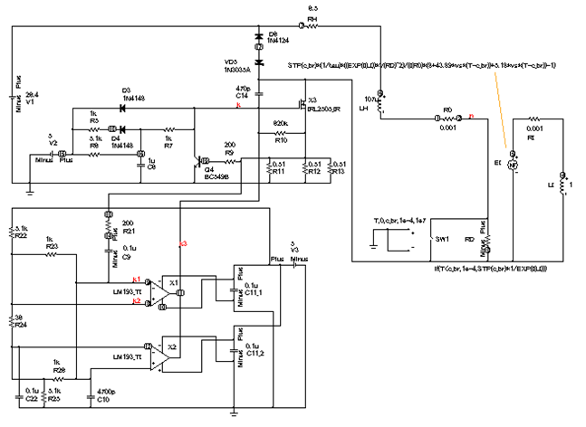
Figure 2 - Scheme of calculation for the opening of the barrier discharge spark protection power source such as IPI-24-3
Figure 3 - These dependencies: 1) amperage; 2) comparator voltage; 3) arc voltage; 4) power; 5) energy; 6) the average power;
Conclusion
The proposed method for calculation of intrinsic safety circuits, called "tubeless methodof thermal evaluation" (MBTO), increases the accuracy of the risk of arcing contacts openwhen the circuit configuration of the complex explosive mixture in the atmosphere due toimprovement of the model calculation of parameters of low-current discharge inexplosion-proof electrical equipment electrical circuits. Researches showed thatincreasing the current setting, you can connect a large inductance, thereby increasing thelength of the line. At the stage of the design and development appropriate to apply the method of thermal evaluation of tubeless intrinsic intrinsically safe circuits with the required parameters, application of which is important when comparing different methods of intrinsic safety, in particular, the measurement of switching off nodes, including the type of power source of FDI 24-3.
References
- Бершадский И.А., Дубинский А.А. Тестирование метода бескамерной тепловой оценки искробезопасности схемы источника питания // Взрывозащищенное электрооборудование: сб. науч. тр. УкрНИИВЭ. - Донецк: УкрНИИВЭ, 2011.- С.230-240.
- Висновок експертизи №1843-2010 від 15.03.2010 р. щодо відповідності обладнення підвищеної небезпеки вимогам нормативно-првових актів з охорони праці та промислової безпеки і можливості його експлуатації в Украйні
- ГОСТ Р 51330.10-99 (МЭК 60079-11-98) «Электрооборудование взрывозащищенное. Часть 11. Искробезопасная электрическая цепь «і» [Электронный ресурс]. – Режим доступа: http://www.ervist.ru/info/normbase/gost51330099.pdf
- Жданкин В.К. Взрывозащищенная выносная система сопряжения с оборудованием нижнего уровня АСУ ТП// Современные технологии автоматизации. 2002.- №2.- С.74 – 84
- Барьеры искробезопасности: шунт-диодные или с гальванической развязкой? Критерии для обоснованного выбора. VSP Technologies & Services [Электронный ресурс]. – Режим доступа: http://www.ervist.ru/info/normbase/gost51330099.pdf
- Павлов Д.Д. Исследование и разработка интеллектуального устройства скробезопасности для систем автоматического управления// Диссертация на соискание ученой степени кандидата технических наук. - Владимир.- 2006,- С. 17-20
- Ковалев А.П. Моделирование параметров разряда и расчетная оценка искробезопасности при размыкании электрической цепи / А.П. Ковалев, И.А. Бершадский, З.М.Иохельсон // Электричество.– 2009.- №11.– С. 62-69.