Abstract
Contents
- Introduction
- 1. Relevance of the subject
- 2. Tasks of the research, expected results
- 3. The main results
- 4. Features of the practical implementation of the fan with the help of SCADA TAC Vista
- Conclusion
- References
Introduction
1. Relevance of the subject
At the present time, there is a large number of engineering equipment in the modern buildings, that needs rational control and management. Characteristics of automatic control systems (ACS) of such a building should with the most efficient modes of its operation providing the optimal operating costs. The cost of the consumed resources and the skills of the personnel are continuously increasing. Thus, the purpose of the ACS of the building equipment is to reduce the cost of the consumed resources, and the operating costs. Therefore the question of the effective use of building automatization systems is very relevant.
2. Tasks of the research, expected results
The main tasks of the research:
1. The review and analysis of the existing diagrams of the central air-conditioning;
2. The investigation of the modes of the executive mechanisms, which are the part of the central air-conditioning installation;
3. The research of the existing methods of the protection and monitoring of engineering equipment, and the search for the new ones;
4. The review of the main problems about SCADA-system and the integration of the various equipment into a single system with the help of SCADA TAC Vista.
To get the results of the research on the development of the new methods of the control and protection of the engineering equipment for the automation and control is the main part of the master degree work.
3. The main results
It is assigned to the building automation subsystem to maintain the required sanitary and hygienic conditions in the building and to ensure its safety and security.
Among the engineering building subsystems it is possible to define:
• ventilation and air conditioning;
• heating (boilers and heat exchangers);
• cooling;
• water supply;
• fire and burglar alarm systems;
• fire protection;
• power and lighting;
• lift and escalator equipment.
Each individual subsystem can include a wide range of controllable process parameters and control signals. One of the most important systems in the modern building is air-conditioning system (ACS). Systems that use sources of heat and cold from the outside are widely used. Such systems are called central air-conditioning systems (CACS) [1].
On the first stage of the research it was considered to use the diagram of the uniflow CACS (fig. 1). For each technology node, that is the part of the system, the table of the used signals to automate the system was created.
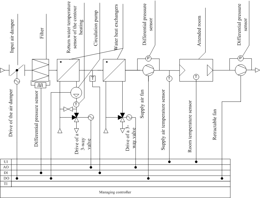
Figure 1 – The diagram of the uniflow CACS with the indicators of the used signals
In order to study issues for the monitoring of the state of buildings engineering equipment, it was decided to observe a separate part of the uniflow CACS and the example of the single engineering system equipment – fan. It is also necessary to develop a system in order to automate and integrate it into the system dispatch TAC Vista.
The digital signals namely:digital output DO (Digital Output) and digital inputs DI (Digital Input) – DI1 and DI2 will be used in order to manage and control the fan. In accordance with the diagram of the fan connection (fig. 2) we use: DO – fan control signal directly from the controller, DI1 – the signal from the differential pressure transducer and DI2 – a status signal of the fan block-contactor. Depending on the values of these signals one can provide information to the operator of the fan work mode (Table 1).
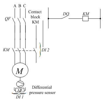
Figure 2 – The diagram of the fan switching
Table 1 – The control on the fan operation mode
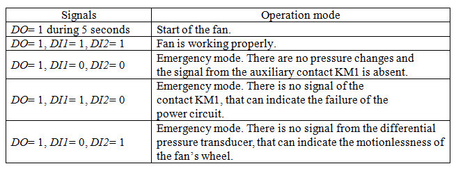
The control of the fan can be implemented with the help of a software package TAC Menta (company Schneider Electric). For the observed signals the functional blocks are created. It is possible to analyze the operation of the fan with the help of these signals. In the TAC Vista system a dispatch to the program should be made. Thus it is possible to realize control of the fan in the system CACS.
Similarly, it is possible to establish the control over other areas of the uniflow CACS. In order to control the elements of the CACS the following types of the signals are used: UI (Universal Input), DI (Digital Input), AO (Analog Output) and DO (Digital Output).
As it has already been mentioned, knowing the status of the output signal to the automation system it is possible to get the information about some engineering equipment, that in its turn, can improve the energy performance of the system, reliability, and optimize the system as a whole.
In order to protect the electric motors that are used in ventilation and air conditioning, PTC-type thermistors are used (Positive Temperature Coefficient) [9]. They are placed in the windings of the motor (it is the maximum heating temperature of stator winding insulation for this class), during the temperature increase the thermistor resistance increases sharply, that can be fixed.
The thermistor must be connected to the control circuit, that makes it possible to convert the resistance change into a control signal that will turn off the engine from the network (the control signal can be displayed in the dispatch system for the convenience and control of the engine operator). If the temperature of the winding exceeds the temperature of the switching off, the sensor resistance changes according to the temperature change (fig. 3).

Figure 3 – Typical dependence of the resistance and the thermistor PTC temperature
The figure illustrates the following points: the characteristic temperature (Tref), the resistance value at the achieved TRef (RRef), minimum temperature and the resistance of the thermistor, TRmin and Rmin.
As a result of these changes in the internal relay the control circuit of the external contactor is de-energized. The motor is cooled and an acceptable motorwinding temperature is recovered, the sensor resistance decreases to the initial level.
Also, the thermistors are placed in the specially provided nests in the frontal parts of the motor (protection against jamming of the rotor). As a rule the engine should be equipped with thermistors in the case of the low speed running and insufficient cooling. PTC thermistors have an indicator such as temperature change or a NAT (Normal Excitation Temperature – normal temperature of excitation). In the motor windings three series-connected thermistors are usually installed, but also six connected thermistors can be installed (two in each winding).
The control of the thermal condition of the engine with SCADA systems can be organized for the automation systems. The diagram, which reveals the essence of controlling the thermal state of the engine is shown on fig. 4.

Figure 4 – Functional diagram of the control motor thermal state in the SCADA system
Thermistors of the PTC-type can be set not only in the engine for the control of the thermal state.
4. Features of the practical implementation of the fan with the help of SCADA TAC Vista
The next step was to develop an automation program for the TAC Xenta controllers, software (SW) TAC Menta for its further integration into the dispatch TAC Vista.
Let three controllers operate the fan (TAC Xenta 401, TAC Xenta 422A and TAC Xenta 302). The process and logic in the TAC Xenta 401 and TAC Xenta 422A is implemented directly. The value of the inputs from the command to switch and the command about the pressure change should be sent via the network from TAC Xenta 302 into TAC Xenta 401. TAC Xenta 401 and TAC Xenta 302 controllers act as the main and TAC Xenta 422A is an additional controller – expansion module for the TAC Xenta 401.
In the TAC Xenta 401 and TAC Xenta 422A the process of the logic control is implemented immediately. In the TAC Xenta 302 the value of the inputs and the pressure changes are sent to the TAC Xenta 401 controller via the network. TAC Xenta 401 and TAC Xenta 302 controllers act as the main ones while TAC Xenta 422A is an additional controller or the expansion module for the TAC Xenta 401.
The configuration of the selected equipment should be added first of all in the TAC Menta Software. Then the program must be developed. As the result it is possible to obtain the program scheme of the fan, which is shown on fig. 5

Figure 5 – Block diagram of the fan in TAC Menta
By developing this program signals DI BKJI and dP come across the network from the TAC Xenta 302 controller. These signals are responsible for pushing the buttons on the stand. The program, which is implemented in the controller TAC Xenta 302 is shown on fig. 6.

Figure 6 – The program that sends the signal values via the network
The next step was to create a network connection to controllers via the network and download programs directly to the controller.
The connection via LonTalkAdapter should be established, that is used as a network interface of the firms Loytec.
Let’s create a TAC Vista network, and add a desired group of controllers. In addition to the TAC Graphics Software the illustration was painted for convenient and user-friendly display of the fan for the operator (fig. 7).
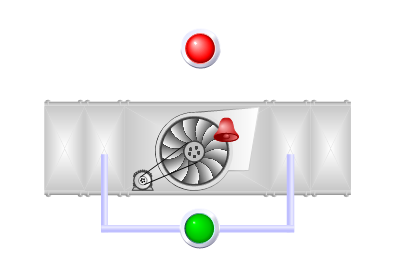
Figure 7 – The fan that was made in TAC Graphics Editor
Let’s initialize and load the developed programs into the controllers and put them in the Online state. Then, it is possible to start the work with the finished program (fig. 8, fig. 9).
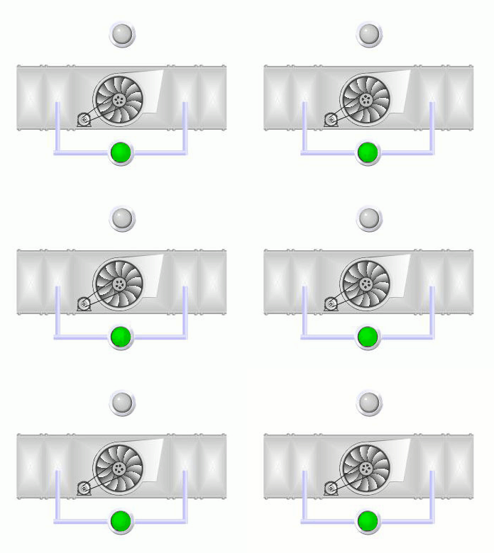
Figure 8 – Example of the fan operation in the TAC Vista
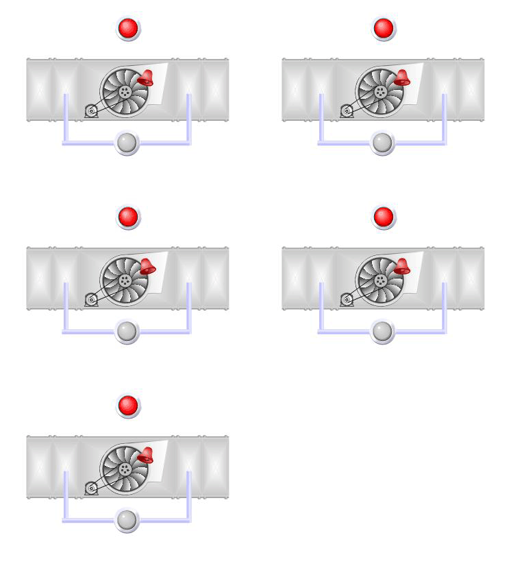
Figure 9 – Example of the protection activation in the program and alert to the operator about an accident
Conclusion
During the organization of the engineering equipment control in the dispatch system it is possible to follow the statistics of failures, emergency situations, as well as automatization of the the repair work. That’s why the issues in the master's research are interesting, and they may find practical application later.
Comment
At this moment the abstract of the master degree work is not completed. Final date of completion: December 2012. After this date, the full text of the work and materials on the topic can be obtained from the adviser.
References
- Бондарь Е.С., Гордиенко А.С., Михайлов В.А, Нимич Г.В. Автоматизация систем вентиляции и кондиционирования воздуха: учебное пособие для студентов высших учебных заведений. – К.: ТОВ
Видавничий будинок
, 2005 – 560с.Аванпост-Прим
- Нимич Г.В., Михайлов В.А, Бондарь Е.С. Современные системы вентиляции и кондиционирования воздуха. – К.: ТОВ
Видавничий будинок
, 2003 – 626с.Аванпост-Прим
- Данилов О.Л., Костюченко П.А. Практическое пособие по выбору и разработке энергосберегающих проектов: в 7 разделах. – ЗАО Технопромстрой, 2006 – 668с.
- Нестеров А.Л. Проектирование АСУТП. Методическое пособие. Книга 1 – СПб Издательство ДЕАН, 2006. – 552 с.
- Андреев Е.Б, Куцевич Н.А., Синенко О.В. SCADA-системы – Взгляд изнутри – М.: Издательство
РТСофт
, 2004. – 176 с. - Пиаришвили Ш.А. Кондиционирование и вентиляция. Учебное пособие для магистров – Рыбинск, 2002. – 80 с.
- Стефанов Е.В. – СПб.: Издательство
АВОК Северо-Запад
, 2005. – 404 с. - Catalog Schneider Electric
Интеллектуальное здание TAC
, 2008 – 174с. - Handbook Grundfos
Электродвигатели
, 2006. – 240 с. - Specialized site
АВОК
- The site of the journal
СТА
