A Tutorial on Visual Servo Control
Автор: S. Hutchinson, G.D. Hager, P. I. Corke
Источник: IEEE Transactions on robotics and automation, vol. 12, no. 5, october 1996
Abstract
This article provides a tutorial introduction to visual servo control of robotic manipulators. Since the topic spans many disciplines our goal is limited to providing a basic conceptual framework. We begin by reviewing the prerequisite topics from robotics and computer vision, including a brief review of coordi-nate transformations, velocity representation, and a description of the geometric aspects of the image formation process. We then present a taxonomy of visual servo control systems. The two major classes of systems, position-based and image-based systems, are then discussed in detail. Since any visual servo system must be capable of tracking image features in a sequence of images, we also include an overview of feature-based and correlation-based methods for tracking. We conclude the tutorial with a number of observations on the current directions of the research field of visual servo control.
Introduction
The vast majority of today's growing robot population operate in factories where the environment can be contrived to suit the robot. Robots have had far less impact in applications where the work environment and object placement cannot be accurately controlled. This limitation is largely due to the inherent lack of sensory capability in contemporary commercial robot systems. It has long been recognized that sensor integration is fundamental to increasing the versatility and application domain of robots, but to date this has not proven cost effective for the bulk of robotic applications, which are in manufacturing. The "frontier" of robotics, which is operation in the everyday world, provides new impetus for this research. Unlike the manufacturing application, it will not be cost effective to reengineer our world to suit the robot.
Vision is a useful robotic sensor since it mimics the human sense of vision and allows for noncontact measurement of the environment. Since the early work of Shirai and Inoue (who describe how a visual feedback loop can be used to correct the position of a robot to increase task accuracy), considerable effort has been devoted to the visual control of robot manipulators. Robot controllers with fully integrated vision systems are now available from a number of vendors. Typically visual sensing and manipulation are combined in an open–loop fashion, "looking" then "moving". The accuracy of the resulting operation depends directly on the accuracy of the visual sensor and the robot end–effector.
An alternative to increasing the accuracy of these subsystems is to use a visual – feedback control loop that will increase the overall accuracy of the system a principal concern in most applications. Taken to the extreme, machine vision can provide closed–loop position control for a robot end–effector – this is referred to as visual servoing. This term appears to have been first introduced by Hill and Park in 1979 to distinguish their approach from earlier "blocks world" experiments where the system alternated between picture taking and moving. Prior to the introduction of this term, the less specific term visual feedback was generally used. For the purposes of this article, the task in visual servoing is to use visual information to control the pose of the robot's end–effector relative to a target object or a set of target features. The task can also be defined for mobile robots, where it becomes the control of the vehicle's pose with respect to some landmarks.
Since the first visual servoing systems were reported in the early 1980s, progress in visual control of robots has been fairly slow, but the last few years have seen a marked increase in published research. This has been fueled by personal computing power crossing the threshold that allows analysis of scenes at a sufficient rate to "servo" a robot manipulator. Prior to this, researchers required specialized and expensive pipelined pixel processing hardware. Applications that have been proposed or prototyped span manufacturing (grasping objects on conveyor belts and part mating), teleoperation, missile tracking cameras, and fruit picking, as well as robotic ping-pong, juggling, balancing, car steering, and even aircraft landing. A comprehensive review of the literature in this field, as well the history and applications reported to date, is given by Corke and includes a large bibliography.
Visual servoing is the fusion of results from many elemental areas including high-speed image processing, kinematics, dynamics, control theory, and real-time computing. It has much in common with research into active vision and structure from motion, but is quite different from the often described use of vision in hierarchical task–level robot control systems. Many of the control and vision problems are similar to those encountered by active vision researchers who are building "robotic heads". However the task in visual servoing is to control a robot to manipulate its environment using vision as opposed to just observing the environment.
Given the current interest in visual servoing it seems both appropriate and timely to provide a tutorial introduction to this topic. Our aim is to assist others in creating visually servoed systems by providing a consistent terminology and nomenclature, and an appreciation of possible applications. To assist newcomers to the field we will describe techniques which require only simple vision hardware (just a digitizer), freely available vision software, and which make few assumptions about the robot and its control system. This is sufficient to commence investigation of many applications where high control and/or vision performance are not required.
One of the difficulties in writing such an article is that the topic spans many disciplines that cannot be adequately addressed in a single article. For example, the underlying control problem is fundamentally nonlinear, and visual recognition, tracking, and reconstruction are fields unto themselves. Therefore we have concentrated on certain basic aspects of each discipline, and have provided an extensive bibliography to assist the reader who seeks greater detail than can be provided here. Our preference is always to present those ideas and techniques that we have found to function well in practice and that have some generic applicability. Another difficulty is the current rapid growth in the vision–based motion control literature, which contains solutions and promising approaches to many of the theoretical and technical problems involved. Again we have presented what we consider to be the most fundamental concepts, and again refer the reader to the bibliography.
Camera Projection Models
To control the robot using information provided by a computer vision system, it is necessary to understand the geometric aspects of the imaging process. Each camera contains a lens that forms a 2D projection of the scene on the image plane where the sensor is located. This projection causes direct depth information to be lost so that each point on the image plane corresponds to a ray in 3D space. Therefore, some additional information is needed to determine the 3D coordinates corresponding to an image plane point. This information may come from multiple cameras, multiple views with a single camera, or knowledge of the geometric relationship between several feature points on the target. In this section, we describe three projection models that have been widely used to model the image formation process: perspective projection, scaled orthographic projection, and affine projection. Although we briefly describe each of these projection models, throughout the remainder of the tutorial we will assume the use of perspective projection.
For each of the three projection models, we assign the camera coordinate system with the x– and y–axes forming a basis for the image plane, the z–axis perpendicular to the image plane (along the optical axis), and with origin located at distance λ behind the image plane, where λ is the focal length of the camera lens. This is illustrated in Figure 1.
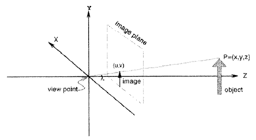
Figure 1 – The coordinate frame for the camera/lens system.
Camera Configuration
Visual servo systems typically use one of two camera configurations: end–effector mounted, or fixed in the workspace.
The first, often called an eye–in–hand configuration, has the camera mounted on the robot's end–effector. Here, there exists a known, often constant, relationship between the pose of the camera(s) and the pose of the end–effector. We represent this relationship by the pose Xc. The pose of the target3 relative to the camera frame is represented by Xt- The relationship between these poses is shown in Figure 2.
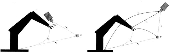
Figure 2 – Relevant coordinate frames (world, end-effector, camera and target) for end–effector mounted, and fixed, camera configurations.
The second configuration has the camera(s) fixed in the workspace. In this case, the camera(s) are related to the base coordinate system of the robot by Xc and to the object by Xt. In this case, the camera image of the target is, of course, independent of the robot motion (unless the target is the end–effector itself). A variant of this is for the camera to be agile, mounted on another robot or pan/tilt head in order to observe the visually controlled robot from the best vantage.
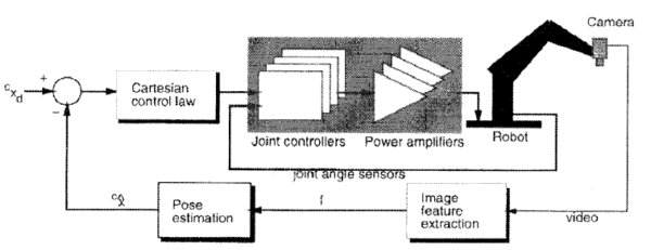
Figure 2 – Dynamic position–based look–and–move structure.
For either choice of camera configuration, prior to the execution of visual servo tasks, camera calibration must be performed in order to determine the intrinsic camera parameters such as focal length, pixel pitch and the principal point. A fixed camera's pose, Xc, with respect to the world coordinate system must be established, and is encapsulated in the extrinsic parameters determined by a camera calibration procedure. For the eye–in–hand case the relative pose, (Xc. must be determined and this is known as the hand/eye calibration problem. Calibration is a long standing research issue in the computer vision community.
Discussion
This paper has presented a tutorial introduction to robotic visual servo control, focusing on the relevant fundamentals of coordinate transformations, image formation, feedback algorithms, and visual tracking. In the interests of space and clarity, we have concentrated on presenting methods that are well–represented in the literature, and that can be solved using relatively straightforward techniques. The reader interested in a broader overview of the field or interested in acquiring more detail on a particular area is invited to consult the references we have provided. Another goal has been to establish a consistent nomenclature and to summarize important results here using that notation.
It is appropriate to note that despite the long history and intuitive appeal of using vision to guide robotic systems, the applications of this technology remain limited. To some degree this has been due to the high costs of the specialized hardware and the diverse engineering skills required to construct an integrated visually controlled robot system. Fortunately the costs of key elements such as cameras, framestores, image processing hardware and computers in general, continue to fall and appear set to do so for some time to come. Cameras are now becoming available with performance characteristics such as frame rate and image resolution beyond the limiting broadcast television standards which have constrained them for so long.
In conclusion we hope that this paper has shown that visual servoing is both useful and achievable using technology that is readily available today. In conjunction with the cost trends noted above we believe that the future for visual servoing is bright and will become an important and common control modality for robot systems in the future.
References
1. Y. Shirai and H. Inoue, "Guiding a robot by visual feedback in assembling tasks," Pattern Recognit., vol. 5, pp. 99–108, 1973
2. P. Corkc, "Visual control of robot manipulators—A review," in Visual Servoing K. Hashimoto. Ed. Singapore: World Scientific, 1993, pp. 1–31. (vol. 7 of Robotics and Automated Systems).
3. G. D. Hagcr, "The "X–vision" system: A general purpose substrate for real–time vision-based robotics," in Proc. Workshop on Vision for Robots, 1995, pp. 56–63, 1995. Also available as Yale CS–RR–1078.
4. B. K. P. Horn, Robot Vision. Cambridge, MA: MIT Press, 1986
5. N. Hollinghurst and R. Cipolla, "Uncalibrated stereo hand eye coordination," Image and Vision Computing, vol. 12, no. 3, pp. 187–192, 1994.
6. W. Jang, K. Kim, M. Cluing, and Z. Bien, "Concepts of augmented image space and transformed feature space for efficient visual servoing of an "eye–in–hand robot" Robolica, vol. 9, pp. 203–212, 1991.
7. N. P. Papanikolopoulos, P. K. Khosla, and T. Kanade, "Visual tracking of a moving target by a camera mounted on a robot: A combination of vision and control." IEEE Trans. Robot. Automat., vol. 9, no. 1, pp. 14–35. 1993.
8. D. E. Whitney. "The mathematics of coordinated control of prosthetic arms and manipulators," J. Pyn. Syst., Meas. Control, vol. 122, pp. 303–309, Dec. 1972.
9.A. Rizzi and D. Koditschek, "An active visual estimator for dexterous manipulation," in Proc. IEEE Int. Conf. on Robotics and Automation, 1994.
10.D. DeMenthon and L. S. Davis, "Exact and approximate solutions of the perspective–three–point problem," IEEE Trans. Pattern Anal. Machine Intell, no. 11, pp. 1100–1105, 1992.
11.G. H. Rosenfield, "The problem of exterior orientation in photogram–metry," Photogrammelric Eng., pp. 536–553, 1959.