Назад
в библиотеку
Prototyping a Three-link Robot
Manipulator
The
authors:
Tarek M. Sobh, Mohamed Dekhil, Thomas C. Henderson, and Anil Sabbavarapu
Source:
Department
of Computer Science and Engineering
University of Bridgeport
Bridgeport, CT 06601, USA
and
Department of Computer Science
University of Utah
Salt Lake City, UT 84112, USA
Abstract
In this paper we will present
the stages
of designing and building a three-link robot manipulator prototype that
was built as part of a research project for
establishing a prototyping
environment for robot manipulators. Building this robot enabled us
determine the required
subsystems and interfaces to build the prototyping environment,and
provided hands-on experience for the real problems and difficulties
that we would like to
address and solve using this environment. Also, this robot is used as
an educational tool in
robotics and control
classes.
1
Introduction
Teaching robotics in most
engineering schools lakes the practical side and usually students end
up taking
lots of theoretical background and mathematical basis, and maybe
writing some simulation programs,
but they do not get the chance to apply and practice what they have
learned on real robots. This is due
to the fact that most of the robots available in the market are either
too advanced, complicated, and
expensive(e.g., specialized industrial robots),or toy-likerobots which
are too trivial and does not give
the required level of depth or functionality needed to demonstrate the
main concepts of robot design
and control. One of our goals in this project, was to build a robot
that is simple, flexible, and easy to
use and connect to any workstation or PC, and at the same time, is
capable of demonstrating some of
the design and control concepts. We also tried to keep the cost as low
as possible to make it available
to any engineering school or industrial organization.
We consider the main
contribution of this work to be building URK (Utah Robot Kit) which is
a
three-link robot prototype that has a small size and reasonable weight
which is convenient for a small laboraclassroom.
URK can be connected to any workstation or PC through the standard
serial port with
an RS232 cable, and can be controlled using a software controller with
a graphical user interface. This
software controller applies a simple PID control low for each
link which doesnot require the knowledge
of the robot parameters. Therfore, this software can be used to control
any electro-mechanical system
that can be controlled by a physical PID controller. The interface
enables the user to change any of the
control parameters and to monitorthe behaviorof the system with an
on-linegraphs and a 3-D viewfor
the robot showing the current positionof the robot.
2
Background and Related Work
Controlling and simulating a
robot is a process that involves a large number of mathematical
equations.
To be able to deal with the required amount of computation, it is
better
to divide them into modules, in
which each module accomplishes a certain task. The most important
modules, as described in [2], are
kinematics, inverse kinematics, dynamics, trajectory generation, and
linear feedback control.
2.1
Robot Modules
There has been a lot of
research to automate kinematic and inverse kinematic calculations. A
software
package called SRAST (Symbolic Robot Arm Solution Tool) that
symbolically solves the forward and
inverse kinematics for n-degree of freedom manipulators has been
developedby Herrera-Bendezu, Mu,
andCain[5]. The input to this package is the Denavit-Hartenberg
parameters,
and the output is the direct
and inverse kinematics solutions. Another method of finding symbolic
solutions for the inverse kinematics problem was proposed in [11].
Kelmar and Khoslaproposed a method
for automatic generation
of forward and inverse kinematics for a reconfigurable manipulator
system [7].
Dynamics is the study of the forces required to cause the motion.
There are some parallel algorithms
to calculate the dynamics of a manipulator. Several approaches have
been suggested in [8, 9, 10] based
on a multiprocessor controller, and pipelined architectures to speed up
the calculations.
Linear feedback control is used in most control systems for positioning
and trajectory tracking.
Thereare sensors at each joint to measure the joint angle and velocity,
and there is an actuator at each joint to
apply a torque on the neighboring link. The readings from the sensors
will constitute the feedback of
the control system. By choosing appropriate gains we can control the
behavior of the output function
representing the actual trajectory generated. Minimizing the error
between the desired and actual trajectories is ourmain concern. Figure
1 shows a block diagram for the
controller,
and the role of each of
the robot modules in the system.
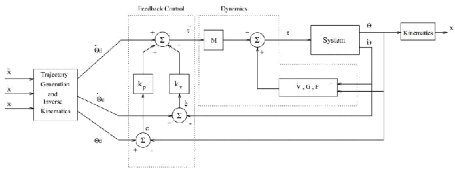
Figure
1 – Block diagram of the Controller of a Robot Manipulator.
2.2
Local PD feedback Control vs Robot Dynamic Equations
Most of the feedback algorithms
used in current control systems are implementations of a proportional
plus derivative (PD) control. In industrial robots, a local PD feedback
control law is applied at each
joint independently. Some ideas have been suggested to enhance the
usabilityof the local PD feedback
law for trajectory tracking. One idea is to add
a lag-lead compensator using frequency response analysis
[1]. Another method is to buildan inner loop stabilizing controller
using a
multivariable PD controller,
and anouter loop tracking controller usinga multivariablePID
controller[12]. In general,usingalocal
PD feedback controller with high update rates can give an acceptable
accuracy for trajectory tracking
applications. It was proved that using a linear PD feedback law is
useful for positioningand trajectory
tracking [6].
3
Prototyping a 3-Link Robot
3.1
Analysis Stage
This project was started with
the study of a set of robot configuration sand analyzed the type and
amount
of calculation involved in each of the robot controller
modules(kinematics,inverse kinematics,dynamics, trajectory planning,
feed-back control, and simulation). This phase was accomplished by
working
through a generic example for a three-link robot to compute
symbolicallythe kinematics, inverse kine-
matics, dynamics, and trajectory planning; these were linked to a
generic motor model and its control
algorithm. This study enabled us to determine the specifications of the
robot for performing various
tasks, it also helped us decide which parts (algorithms) should be
hardwired to achieve specific mechanical performances, and also how to
supply the control signals
efficiently and at what rates.
Первым шагом в разработке
регуляторов для робота-манипулятора является решение его кинематики,
обратной кинематики, динамики и управления с обратной связью, которые
будут использоваться. Кроме того на данном этапе должны быть определены
типы входных данных и пользовательский интерфейс. Мы также должны знать
такие параметры робота как: длины звеньев, их массы, моменты инерции,
расстояния между суставами, конфигурацию робота, и тип сочленения.
Переменные параметры должны
быть заданы так, чтобы контроллер мог
использоваться без каких либо изменений для различных конфигураций.
3.2
Controller Design
The first step in the design of
a controller for a robot manipulator is to solve for its kinematics,
inverse
kinematics, dynamics, and the feedback control equation that will be
used. Also the type of input and
the user interface should be determined at this stage. We should also
know the parameters of the robot,
such as: link lengths, masses, inertia tensors, distances between
joints, the configuration of the robot,
and the type of each link (revolute or prismatic). To make a modular
and flexible design, variable parameters are used that can
be fed to the system at run-time, so that this controller can be used
for different
configurations without any changes.
The kinematics and the dynamics
of the three models have been generated using some tools in the
department called genkin and gendyn that take the configuration of the
manipulator in a certain format
and generate the corresponding kinematics and dynamics for that
manipulator. For the trajectory generation, The cubic polynomials
method
was used. The error in position and velocity is calculated using
the readings of the actual position and velocity from the sensors at
each
joint. Our control module simu-
lated a PID controller to minimize that error. The error depends on
several
factors such as the frequency
of update, the frequency of reading from the sensors, and the desired
trajectory.
3.3
Simulation
A simulation program has been
implemented to study the performance of each manipulatorand the ef-
fect of varying the update frequency on the system. Also it helps to
find approximate ranges for the
required torque and/or voltage, and to determine the maximum velocity
to know the necessary type of
sensors and A/D. To make the benchmarks, as described in the next
section, we did not use a graphical interface to the simulator, since
the drawing routines are time
consuming, and thus give misleading
figures for the speed.
3.4
PID Controller Simulator
As mentioned in Section 2.2, a
simple linear feedback control law can be used to control the robot
manipulator for positioning and trajectory tracking. For this purpose,
a PID controller simulator was developed to enable testing and
analyzing the robot behavior using this control strategy. Using this
control
scheme helps us avoid the complex (and almost impossible) task of
determining the robot parameters
for our three-link prototype robot. One of the most complicated
parameters is the inertia tensor matrix
for each link, especially when the links are nonuniform and have
complicated shapes.
3.5
Building the Robot
The assembly process of the
mechanical and electrical parts was done in the Advanced Manufacturing
Lab (AML) with the help of Mircea Cormos and Prof. Stanford Meek. In
this design the last link is
movable, so that different robot configurations can be used (see Figure
2).
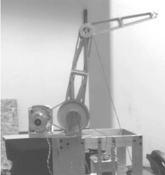
Figure
2 – The physical three-link robot manipulator.
There are three motors to drive
the three links, and six sensors (three for position and three for ve-
locity), to read the current position and velocity for each link to be
used in the feedback control loop.
This robot can be controlled
using analog control by interfacing it with an analog PID controller.
Digital control can also be used by interfacing the robot with either a
workstation (Sun, HP, etc.) or a
PC via the standard RS232. This requires an A/D and D/A chip to be
connected to the workstation (or
4
thePC) and an amplifierthat provides enough power to drive the motors.
A summary ofthis designcan
be found in [3, 4].
4
Testing and Results
4.1
Simulator for three-link Robot
This simulator was used to give
some rough estimates about the required design parameters such as
linklengths, linkmasses, updaterate, feedback gains,etc. It isalso used
in the benchmarking described
earlier. This simulator uses an approximate dynamic model for the
robot, and it allows any of the design
parameters to be changed.
4.2
Software PID Controller
A software controller was
implemented for the three-linkrobot. This controller uses a simplelocal
PID
control algorithm, and simulates three PID controllers; one for each
link. Several experiments and tests
have been conducted using this software to examine the effects of
changing some of the control parameters on the performance of the
robot.
The control parameters that can
be changed in this program are:
- forward gain
- proportional gain
- differential gain
- integral gain
- input trajectory
- update rate
In these experiments, the
program was executed on a Sun SPARCStation-10, and the A/D chip was
connected to the serial port of the workstation. One problem we
encountered with this workstation is
thes low protocol for reading the sensor data, sinceit waits for an
I/Obuffer to be filled before it returns
control to the program. We tried to change the buffer size or the
time-out value that is used, but we
had no success in that. This problem causes the updaterate to be very
low (about 30 times per second),
and this affects the positional accuracy of the robot. We were able to
solve this problem on an HP-700
machine, and we reached an update rate of 120 times per second which
was good enough for our robot.
5
Conclusion
A prototype 3-link robot
manipulator was built to determine the required components fo ra
flexible prototyping environment for electromechanical systems in
general, and for robot manipulators in particular. A local linear PD
feedback law was used for controlling the robot for positioning and
trajectory
tracking. A graphical user interface was implemented for controlling
and simulating the robot. This
robot is intended to be an educational tool, therefore it was designed
in such a way that makes it very
easy to install and manipulate.
References
- CHEN, Y. Frequency
response
of discrete-time robot systems -
limitations of pd controllers and
improvements by lag-lead compensation. In IEEE Int. Conf. Robotics and
Automation (1987),
pp. 464–472.
- CRAIG, J. Introduction To
Robotics. Addison-Wesley, 1989.
- DEKHIL, M., SOBH, T. M., AND
HENDERSON, T. C. URK: Utah Robot Kit
- a 3-link robot
manipulator prototype. In IEEE Int. Conf. Robotics and Automation (May
1994).
- DEKHIL, M., SOBH, T. M.,
HENDERSON, T. C., AND MECKLENBURG, R.
Robotic prototyping
environment (progress report). Tech. Rep. UUCS-94-004, University of
Utah, Feb. 1994.
- HERRERA-BENDEZU, L. G., MU,
E., AND CAIN, J. T. Symbolic
computation of robot manipulator kinematics. In IEEE Int. Conf.
Robotics and Automation (1988), pp. 993–998.
- KAWAMURA, S., MIYAZAKI, F.,
AND ARIMOTO, S. Is a local linear pd
feedback control law
effictive for trajectory tracking of robot motion? In IEEE Int. Conf.
Robotics and Automation
(1988), pp. 1335–1340.
- KELMAR, L., AND KHOSLA, P.
K. Automatic generation of forward and
inverse kinematics for
a reconfigurable manipulator system. Journal of Robotic Systems 7, 4
(1990), pp. 599–619.
- LATHROP, R. H. Parallelism
in manipulator dynamics. Int. J.
Robotics Research 4, 2 (1985), pp.
80–102.
- LEE, C. S. G., AND CHANG, P.
R. Efficient parallel algorithms for
robot forward dynamics computation. In IEEE Int. Conf. Robotics and
Automation (1987), pp. 654–659.
- NIGAM, R., AND LEE, C. S. G.
A multiprocessor-based controller
for mechanical manipulators.
IEEE Journal of Robotics and Automation 1, 4 (1985), pp.
173–182.
- RIESELER, H., AND WAHL, F.
M. Fast symbolic computation of the
inverse kinematics of robots.
In IEEE Int. Conf. Robotics and Automation (1990), pp.
462–467.
- TAROKH, M., AND SERAJI, H. A
control scheme for trajectory
tracking of robot manipulators.
In IEEE Int. Conf. Robotics and Automation (1988), pp.
1192–1197.