
Electric drive and automation of industrial plants
Electromechanical systems of automation and electric drive
At present, the increased interest is the electric induction, performed on the basis of autonomous current inverter with pulse width modulation. This is due to the significant advantages of this type of induction motor drives, the main ones are: first, – the technical simplicity of the implementation of energy recovery mode in the feeding network, and secondly, – the formation of the stator voltage drop with a small amplitude and reduced the steepness of the fronts (compared with widespread asynchronous electric drives based on the autonomous voltage inverter with pulse width modulation).
Rationale for master's thesis topic: The question of resources and energy are directly related to the introduction of high-frequency control for a specific electric power. In this regard, there is actual improvement in performance drives with frequency converters.
The main issues to be decided in the work:
At the moment, to semiconductor frequency converter (imposed strict requirements on the quality of the input current consumption of the AC [1]. Regarding frequency converters on the basis of autonomous voltage inverter, these requirements can be met by using an active rectifier voltage, which ensures the formation of nearly sinusoidal current using a pulse-width modulation. When used in stand-alone inverters circuit current inverter is the same problem occurs with the formation of the input current. Its solution is possible when using an active rectifier [2].
The purpose of the work. Develop an algorithm implementation using AVT relay input current regulation principle and thus perform modeling of processes in distillation scheme.
The scheme of the active rectifier includes a matching transformer (if required), three-phase bridge with IGВT chokes in DC link and input LC – filter.
In order to form an active input current rectifier uses three relay control for each of the members of the active phase rectifier. Is given by the deviation δ of the active phase of the input current rectifier voltage relative to a given value of іф with respect to a given value iзад. So much for the positive half-wave, if iф < ізад + δ, then the generated signal is Р = 1 provides the key to activate the flow of the active phase of the input rectifier current of positive polarity, otherwise Р = 0. For the negative half-wave signal is formed in a similar way to the N key switch ensures the flow of the active phase of the input rectifier current of negative polarity.
The algorithm of the active rectifier provides unlocking of two keys in different arms of the bridge (the load is connected to the source). When the load is disconnected from the source, open both keys in one arm of the bridge to close the current output circuit. Circuit operation is carried out in accordance with the signals of the clock generator, which generates two sequences (direct – n and inverse – m) with a frequency modulation ƒм = 1 / Tм. The duration of the clock pulse (stroke work) corresponds to half the modulation period and defines the zone of the relay controller. The period of the output voltage is divided into six intervals of work. At each interval the currents of the two phases have the same polarity (for example, a and c), the current third phase (например, в) has the opposite polarity. Then the cycle n keys open in phases a and в, on the stroke m keys open in phases c and в. In this key phase in the open during the whole service, for the closure of the keys in the phases а and с and the unlocks в, and the second key phase than is achieved by closing the load current.
Modeling of the active rectifier circuit was carried out using the software package MATLAB. Block diagram of the model shown in Figure 1. The model includes three-phase IGBT bridge management system SU, the input circuit (Input link).
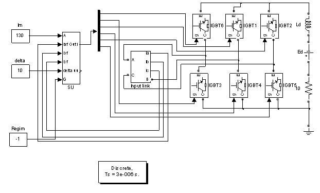
Figure 1 – A model for the study of the active rectifier
Form an output circuit smoothing choke Ld, resistive load and a source of EMF (Ed). Input circuit includes a three-phase AC power supply and input smoothing LC filter. Are given by the amplitude of the input current Im, given the deviation δ (delta). We considered two modes of operation Active Rectifier: Rectifier with the transfer of energy in the chain of the rectified current (load active and Ed = 0) and the inverter in the reverse direction of energy transfer (Ed > 0). Changing the phase of the input current is active rectifier on the input G (Regim = 1 for φ= 0 and Regim = - 1 for φ = π).
Oscillograms of the voltage phase of the network uA, the current phase of the network iФА, current phase active rectifier current in the input filter і¹ФА, the rectified current іd are shown in Figure 2. In this case the input current harmonic distortion iФA considering harmonics up to the 37th was 5.26%.
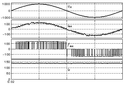
Figure 2 – Oscillograms of the active rectifier
In the high-voltage inverter circuit in the active rectifier uses a serial connection keys. In this paper we proposed to use a serial connection of several active rectifier for feeding them from the isolated secondary windings of the transformer input. This eliminates the question of balancing the stresses of keys and allows to solve the problem in improving the harmonic content of input current of the transformer without increasing the switching frequency of key active rectifier.
Electric drive is an integral part of conservation. This is largely for AC Motors High Power, which uses high-voltage induction motors. At the same time come to the fore issues of quality power conversion and inverter are increased requirements [1]. For high-voltage electric alternating current "classical" solution is the use of cascade multilevel inverters such as «Perfect Harmony», where the scheme is quite complex, and at a voltage of 6 kV single-phase contains six independent inverters voltage at the output stage. The input circuit contains 18 rectifiers with capacitive filters, which are powered by a transformer with 18 sets of secondary windings.
A more simple and promising solution in terms of obtaining a sinusoidal voltage output is possible on the basis of autonomous current inverter with an output capacitor filter using a pulse-width modulation [1 – 4]. The more that the form of a sinusoidal voltage is provided close to the entire range of output frequency regulation. There are solutions of high-frequency converters based on the autonomous current inverter [1], which are quite successful in competition with multi-level inverters, for example, Power Flex 7000 (firm «Rockwell Automation").
The structure of the power circuits of frequency converters on the basis of autonomous current inverter in conjunction with an active rectifier is much simpler than the multi-level inverters. The scheme of the autonomous current inverter performed on locked by the control circuit thyristors with large losses in the switch. This limits the output current of the formation of an autonomous current inverter. To reduce the number of switches used by the election of pulse-width modulation [1] with the suppression of higher harmonics (5th, 7th, 11th) in seven half-wave pulses in the inverter output current is independent of current. At the same time according to [1] Harmonic (THD) of output current autonomous current inverter is overvalued and is about 5%. Slightly better performance for the output voltage and current autonomous current inverter are obtained in [3, 4] using the relay controller to generate the load current.
Known solutions applied autonomous current inverter [1 – 4] focused on the formation of the current. However, the question of autonomous current inverter as a source of sinusoidal voltage at a given time is insufficiently studied. Simplify the problem of high-power applications with frequency converters according to quality of output voltage and input current standards [5] at this time is important. Her decision will help to expand applications of high-frequency converters. At the same time promising is the use of frequency converters on the basis of autonomous current inverter and low voltage electric drive, where they may be able to compete with the "classical" solution based on a two-level inverter with active voltage rectifier.
The purpose of the work. Develop principles of autonomous current inverter mode sinusoidal voltage source.
This should solve the following problems:
Scheme of three-phase bridge inverter current stand-alone locked the keys on the control circuit (Figure 3) contains the output capacitor filters the higher harmonics, which also provides the switching of the load current when locking keys autonomous current inverter. Regardless of the algorithm generates an autonomous current inverter output current іи pulse shape, which is the sum of the capacitor current іс and the load iн (iи=iс+iн). The form of the inverter output voltage independent current is close to sinusoidal. With a pulsating output current autonomous current inverter capacitor filter is substantially changes its mode of operation, which complicates the task of obtaining a sinusoidal load current.
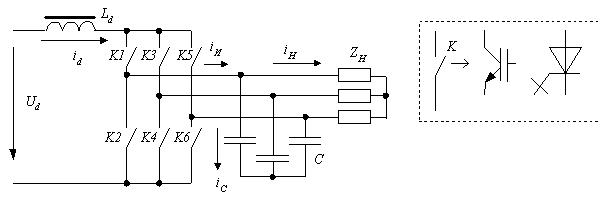
Figure 3 – Structure of the power circuits autonomous current inverter
The principle of autonomous control inverter power source mode sinusoidal output voltage. It uses three relay voltage regulator for δ each of the output phases autonomous current inverter, which is given by the tolerance Uф output phase voltage with respect to a given value Uзад = U1m sin ωt.
So much for the positive half-wave Uф, if Uф < Uзад + δ, then the generated signal is P = 1 to activate the key, ensuring the flow of the output phase of the autonomous current inverter current of positive polarity, otherwise P = 0. For the negative half-wave Uф similarly shaped signal N N to activate the key, ensuring the flow of the output phase of the autonomous current inverter current of negative polarity.

Figure 4 – Vector diagram for the stand-alone inverter output phase current
Pulse shaping key management autonomous current inverter is carried out in accordance with the first harmonic current iи (Fig. 4), which lags by β of the voltage Uф. The output voltage with a base value against which the currents are determined by the autonomous current inverter circuit. It is necessary to consider the following features of an autonomous current inverter circuit for switching the current source Id:
The principle of forming an autonomous inverter output voltage is illustrated in Figure 5 the current, where the period of the output voltage is divided into six intervals (τ1 – τ6). On the interval τ1 currents in the output phases а and с positive and are formed when unlocking key corresponding К1 and К5 relay controls (Ра and Рс). The current in phase with в negative and flows through a permanent public key К4. For locking the keys К1 and К5 unlocked the key to phase К3 providing a flow of current source К3 and К4.
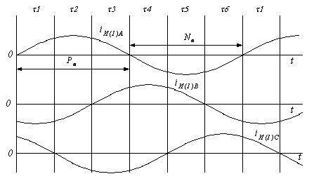
Figure 5 – The principle of the formation of output voltage of the autonomous current inverter
Voltage key management prepared in accordance with the equations:
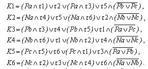
The values of the variables that take a single value τi = 1 for the corresponding intervals (τ1 – τ6) are determined by the phase β of output current autonomous current inverter voltage with respect to the task. The value of the β in the vector system can be calculated from the current components of Isy and Isx. It should be noted that this algorithm requires the minimum number of switching keys, as in the sixth period of the output switching frequency and the corresponding key is not an autonomous current inverter is open all the time.
The current value Id inlet autonomous current inverter is given for the following reasons. The minimum value at which the working out of the specified output voltage is determined by the autonomous current inverter output current of the first harmonic Idмин = Iиm(1). This corresponds to the amplitude modulation factor μ = 1 and the minimum number of key switches the autonomous current inverter. The voltage at the input of the autonomous current inverter Ud maximum, its value can be determined on the basis of equality of active power at the input and output of an autonomous current inverter (losses in the scheme of autonomous current inverter is neglected).
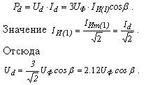
If the input is an autonomous current inverter as a current source is used for three-phase rectifier bridge circuit, the maximum value of Ud = 2.34Uфс (Uфс – phase AC). Thus, the implementation of the frequency converter based on the current stand-alone inverter is possible with a direct connection to the network without a transformer, and there is a possibility of some increase in the autonomous current inverter voltage, for example, by increasing the frequency of the output voltage above 50 Hz.
The higher the value Id > Idмин modulation factor μ decreases at a constant value Iиm(1). Thus, the system adaptable to the task and does not require precise calculation of current value Id, β – as occurs in conventional systems to work in source mode. The same can be noted in relation to the value of the μ except for some deterioration in waveform. However, at lower switching frequency ƒм increases, which leads to increased energy losses in them.
The frequency shift key autonomous current inverter is also determined by a given value of the deviation δ The frequency shift key autonomous current inverter is also determined by a given value of the deviation δ), he choice of the values of Id and frequency shift key. By reducing the amplitude of the output voltage of the voltage at the input Ud autonomous current inverter is reduced in proportion to – switching losses are reduced in the keys, and the value β.
The rate of change of output voltage is determined by the autonomous current inverter output filter capacitance of the capacitor. Is a natural desire to reduce it, but this again leads to an increase in the frequency shift key autonomous current inverter.
Regarding the high-voltage inverter using high-frequency ƒм keys should be minimal, low-voltage key, low-loss switching frequency limits are not determinative.
Simulations were performed using the software package MATLAB.A mathematical model which includes (Fig. 6): three-phase bridge IGBT, the ideal current source to the input job Id, an active-inductive load (Load), the output filter capacitor (filtr), the control system (SU), and set of instruments (in Figure 4 not shown). Specified frequency (ƒ) and the amplitude of the output voltage (Um), given the deviation δ (delta), the angle β(faza).
In practicing the process of research was considered an autonomous current inverter output voltage for different values of circuit parameters, and relay setting voltage regulator. In Table. Figure 6 shows the performance of the autonomous current inverter circuit with RL – load with Zн = 10 ОМ, cos π = 0.8, the filter capacitance С = 90 мкФ ( 47% of the value of filter capacitance required to compensate the reactive power load at 50 Hz) and different values of the current at the input frequency of the output voltage of 50 Hz. When the frequency of the output voltage Id and ƒвых=50 Гц set the value of β = 21.5° (set the value of β = π/8=22.5°). Set value Um = 1250 В, δ = 40 В. The value Idмин = 106 А. (THD) was determined by taking into account the harmonics with the order to 40. For comparison, in [4] achieved Harmonic current THDi=1.56%.
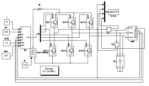
Figure 6 – The model for the study of autonomous current inverter
Table 1 – Simulation results

Oscillograms of the output voltage of the autonomous current inverter (UФ), voltage setting the key К1, the phase inverter output current іи and the current phase of the load ін for ƒвых = 50 Гц are shown in Figure 7.
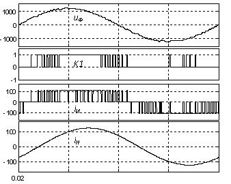
Figure 7 – The oscillograms of output voltage, the voltage setting the key K1 and current AIT
The proposed management principle provides the autonomous current inverter mode sinusoidal voltage source. In this case the harmonic structure of the inverter output voltage independent of current corresponds to the standards [5] in the whole range of output voltage regulation and frequency.
The principles of implementation of the active rectifier using relay controls the input current. The model and simulation results of the active rectifier circuit in the software package MATLAB.
The principles of the implementation of autonomous inverting current mode sinusoidal voltage source using the principles of relay control. The scheme of the model and the simulation results in the inverter circuit software package MATLAB.
The subject of future research is to develop the structure of the automatic control system applied induction motor.
In writing this essay master's work is not yet complete.
Full text of the work and materials on the subject may be obtained from the author or his head after that date.