Автор: G. Cannata, M. Maggiali, G. Metta, G. Sandini
An Embedded Artificial Skin for Humanoid Robots
Abstract
A novel artificial skin for covering the whole body of a humanoid robot is presented. It provides pressure measurements and shape information about the contact surfaces between the robot and the environment. The system is based on a mesh of sensors interconnected in order to form a networked structure. Each sensor has 12 capacitive taxels, has a triangular shape and is supported by a flexible substrate in order to conform to smooth curved surfaces. Three communications ports placed along the sides of each sensor sides allow communications with adjacent sensors. The tactile measurements are sent to embed microcontroller boards using serial bus communication links. The system can adaptively reduce its spatial resolution, improving the response time. This feature is very useful for detecting the first contact very rapidly, at a lower spatial resolution, and then increase the spatial resolution in the region of contact for accurate reconstruction of the contact pressure distribution.
1. Introduction
Tactile sensing is strategic for implementing safe control of robots interacting with humans, objects, and possibly in unstructured conditions. In classical robot interaction tasks (e.g. peg-in-hole problem) where usually interaction is expected or planned at a specific robot locations (typically at the end-effector tip), force/torque sensors have been widely and successfully adopted. On the other hand, for advanced robot systems, e.g. humanoid robots, require the capability of controlling more complex forms of interaction (e.g. whole hand or whole arm grasping and manipulation, gait stability control etc.), where the location and the characteristics of the contact could not be exhaustively predicted or possibly modelled in advance. Then, skin-like sensors and sensing methods for processing distributed tactile information are required in order to enable the implementation of safe interaction strategies.
Tactile sensing for robotic applications has been studied for a long time and a very large number of transduction technologies and design solutions have been reported in the literature [1]. A particular interest has been put on sensor for robotic hands [2-6]. for grasping and manipulation of object.
Recently, with the growing interest for humanoid robots, complex tasks such as walking, interaction with humans, body manipulation, which require contact of the robot with the environment, not only with the hand, but using the whole body [7], have been largely investigated. These tasks require the monitoring of the contacts of the robot with the environment which may happen at unpredictable positions and unpredictable ways (the type of contacts depends on the shape, size and material of the objects in contact). We assume that these tasks could be implemented provided that large scale tactile sensors (robot skin for short) covering large parts of the robot body are available. Such a technology poses several important technical engineering challenges as it must be: conformable to adapt to curved robot body, tough and reliable to withstand a significant number of contact cycles, embedded to allow modular integration with the robots, and finally simple to manufacture.
Various attempts have been made to tackle these issues to develop robot skin systems in the past few years.
Hoshi and Shinoda [8], proposed the amazing idea of constructing tactile sensors based on discrete wireless transducers randomly dispersed in moulded silicone rubber and activated by a wireless link for communication and power supply. This concept, although impressive, does not appear feasible at the present state of the technology. One of the first examples of truly scalable robot skin systems for humanoid robots has been proposed by Ohmura and Kuniyoshi [9]. They approached the problem at system level, and focused the issue of the wiring as the key problem for developing a technology which could be practically exploited. Their main contribution has been that of introducing a networked architecture featuring peripheral nodes (chips) scanning (locally) a limited number of taxels. All the electronics and the transducers are embedded on a tree-shaped flex/semi-flex PCB support. This solution allows a pretty simple mechanical integration of the sensor over curved surfaces and has been experimentally tested An Embedded Artificial Skin for Humanoid Robots Giorgio Cannata, Marco Maggiali, Giorgio Metta and Giulio Sandini with success. On the other end the proposed robot skin has pretty low spatial resolution and, since it is based on optical transducers, in order to limit power consumption has a pretty low sampling rate.
A fault tolerant skin-like tactile sensor based on infrared transducers has proposed by Um and Lumelsky [11], who tackled the problem via component redundancy for a system featuring over 1000 sensing elements.
Another example of artificial skin system for a humanoid robot has been proposed by Ishiguro et al. [10]. The sensor has been designed with the aim of detecting stimuli coming from people trying to interact with the robot and features a PVDF based transducers. The skin has low spatial resolution (transducer area is of about 25 cm2), and due to the characteristics of the transducer, it has the possibility of measuring only stimuli at frequency higher than 5-10 Hz.
In the robot ARMAR-III [12], developed by Dillmann et al., the idea of skin patches, based on piezo-resisteive matrices of sensors, with embedded data processing electronics has been successfully implemented. Embedded electronics provides local tactile data processing in order to limit the bandwidth requirements. The patches are custom designed and have flat or cylindrical shape in 3D for covering relevant parts of the robot arms, while smaller patches are used to sensorize the fingers.
The contribution of this paper is a novel artificial skin for covering the whole body of a humanoid robot. It provides pressure measurements and allows estimating information about the pressure distributions arising during contacts. The present prototype is based on capacitive transducers grouped onto modular sensors providing a spatial resolution of approx. 2 taxels·cm-1. The system is designed to be conformable with complex surfaces. It has low power consumption (about 5 W·m-1). Transduction electronics is embedded on each sensor and separated microcontroller boards drive the data acquisition, early processing and data communication.
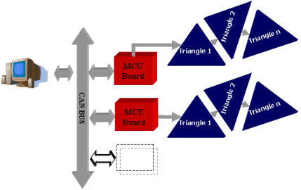
Fig. 1. System Architecture. Up to 16 tactile sensors (for a total of 192 taxels) can be networked and communicate with a microcontroller measuring pressure data and communicating with other modules using a CAN bus.
The structure of the paper is the following. In Section 2 the proposed artificial skin system will be described, and the first prototype developed presented in Section 3 along with preliminary experimental results will be presented the first prototype realized and experiments. Conclusions will finally discuss in Section 4.
2. Artificial skin system
A. The System
The system is based on conformable mesh of sensors having triangular shape and interconnected in order to form a networked structure. Each sensor is supported on a flexible substrate allowing the sensor to conform to smooth curved surfaces, implementing 12 taxels based on capacitive transducers. Three communications ports placed along the sides of the sensor (one for the input from an adjacent sensor, and the others as outputs toward adjacent sensors) allow interconnecting up to 16 sensors. The measurements are sent, using 4 serial bus communication links, to a microcontroller based module which send the tactile data to a host using a CAN bus. The system level concept of the tactile sensor is sketched in fig. 1.
a)
b)
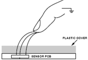
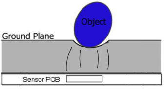
Fig. 2. Concept of the capacitive transducer. (a) Typical model: finger varies circuit capacitance. (b) a compliant ground plane changes the circuit capacitance when deformed by contact pressure.
B. Capacitive Tactile Transducer
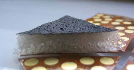
Capacitive pressure transducers have been implemented using commercially available capacitance to digital converter integrated circuits (CDC), commonly used in cell phones. These sensors detect the variation of a capacitance, e.g. due to the presence of a human finger over a copper plate: the closer the finger, the higher the variation. In our design the structure of the capacitor has been modified in order to be able to recognize not only human touch but also objects. As shown in fig. 2, a deformable conductive ground plane is introduced and the effect of contact pressure is a change of circuit capacitance. The ground plane, as show in fig. 3, is implemented by spraying a thin layer of electrically conductive silicon rubber (connected to ground), over a thick (3-5 mm) compliant substrate made of silicone rubber foam, 3-5 mm). In this way, when any object is pressing the silicone rubber, in fact, the ground plane deformation, changes the capacitance value of the circuit. The ground plane forming the outer layer of the sensor has also the benefit of reducing the electrical noise coming from the environment.
C. Triangle Modules
The idea of using a mesh of triangles for covering threedimensional surfaces is inspired by the triangulation technique, widely used in computer graphics. Using triangles in fact, it is possible to approximate complex surfaces such as the ones presented on a humanoid robot, for example, in the arms, legs and thorax. The triangle is the base unit of the proposed tactile sensor. It consists of an offthe- shelf CDC (AD7147 from Analog Device in the present implementation) that provides twelve 16 bits measurements of capacitance. Furthermore the sensor has three communications ports placed along its sides: one for the input from an adjacent triangle, and the others as outputs toward adjacent triangles.
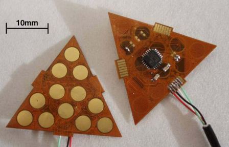
The support of the sensor is a two side flex PCB. On one side are etched 12 circular pads, forming the taxels, acting as armatures of capacitors. On the other side of the PCB is mounted the CDC chip and are etched the three communication ports, as shown in fig. 3. The triangles are interconnected throw the communication ports on the PCB, without using cables. It is possible to connect up to 16 triangles in the presented implementation (fig. 4). A single cable goes from the triangles mesh to the microcontroller, reducing the problem of wire management.
In the first prototype all the triangles are equal in shape and dimension, but it is possible to change the size and the shape in order to better approximate complex surfaces. However the flexibility of the triangle itself gives and advantage in terms of conformability with respect to computer graphic technique where the triangles are considered rigid.
a)
b)
Fig. 3. The triangle module. (a) Each sensor implements 12 taxels and hosts the capacitive transduction electronics. (b) The thick layer of silicone rubber foam covering the sensors and the conductive layer used as ground plane sprayed on top.
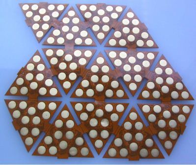
Fig. 4. 16 triangles interconnected on a flexible PCB.
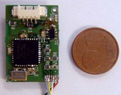
Fig. 5. Microcontroller board. In the current implementation is a small independent module to be embedded inside the robot body.
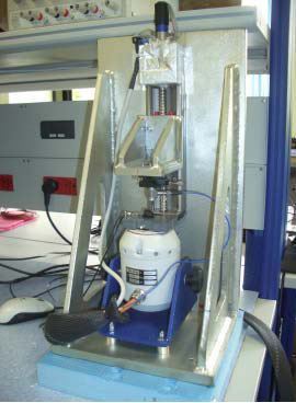
Fig. 6. Experimental set-up. A shaker is moving up and down the sensor and applied pressure is measured by a load cell.
D. Microcontroller Module
The microcontroller unit (fig. 5) is used for programming the CDC chips driving the taxels and for reading the pressure measurements. The microcontroller can also be used to switch to different behaviours of the sensors. In fact, it can be possible to program the CDC in order to get either an average measurement of the 12 taxels at high frequency (about 500 Hz), or reading the 12 measurements independently at a lower frequency up to 50 Hz. Furthermore, as discussed in [6] data processing to preprocess the raw pressure data and reduce the bandwidth requirements to feed-back the tactile information to the higher level control modules, can be also implemented on the microcontroller module.
3. Experiments
Experimental tests have been carried on in order to evaluate the behaviour of a single triangle module. The experimental set-up used for the tests is composed by a PCB 208 C01 dynamic load cell connected to a rigid plate supporting the sensor. A shaker is used to apply pressures on the sensors which are also measured by the load cell (fig. 6). The first experiment is carried on a triangle module in order to evaluate the response of the sensor when an external force is applied on it. Figure 7 shows the result of a uniform sinusoidal pressure modulated in amplitude exert on the whole triangle. In the plot can be seen that the behaviour of the pads are similar to each other and approximate well the load cell profile. The second experiment is done with the same stimulus, but in this case only two of the twelve taxels are pressed. Figure 8 shows the sensor output versus the measured force of those two taxels (green dots and blue dots). In this case the curves are not equal because the load cell is pressing over two electrodes non uniformly.
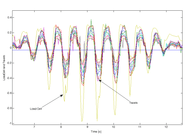
Fig. 7. Time response of the taxels.
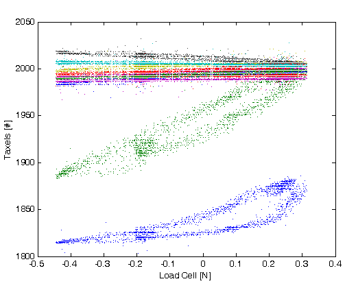
Fig. 8. Sensor characteristics.
4. Conclusion
In this paper we have described the first prototype of an artificial skin system designed for a humanoid robot. The system is based on mesh of triangle sensor modules designed to cover the robot body. Capacitive transduction technology is adopted for measuring the contact forces arising during contact of the robots with the environment. The sensors network is designed to provide a tactile image of the whole robot body. A first prototype with six triangle modules has been realized and quantitative experiments are ongoing, (fig. 9). Next step will be the integration of the skin on the humanoid robot iCub [13].
Future work, exploiting the robot skin technology will enable the study of tactile based control strategies for crawling and interact with humans.
![Fig. 9. Preliminary test for covering the upper arm of the humanoid
robot iCub [13] using the proposed tactile sensor.](images/article_7_9.jpg)
Fig. 9. Preliminary test for covering the upper arm of the humanoid robot iCub [13] using the proposed tactile sensor.
References
[1] M. H. Lee, H. R. Nicholls “Tactile sensing for mechatronics-a state
of the art survey”, Mechatronics, Elsevier, Vol.9, pp1-31. 1999.
[2] H. Liu, P. Meusel, G. A. Hirzinger, "A Tactile sensing System for
the Three-Finger Robot Hand," International Symposium on DLR
Measurement and Control in Robotics, pp. 91-96, 1995.
[3] H. Kawasaki, T. Komatsu, and K. Uchiyama “Dexterous
Anthropomorphic Robot Hand With Distributed Tactile Sensor:
Gifu Hand II” IEEE Transaction on Mechatronics, Vol. 7, No. 3, pp
296-303, 2002.
[4] T. B. Martin, R. O. Ambrose, M. A. Diftler, R. Platt, Jr., M. J.Butzer
“Tactile Gloves for Autonomous Grasping with the NASA/DARPA
Robonaut” Proceedings of the 2004 IEEE International Conference
on Robotics & Automation, New Orleans, LA, April 2004.
[5] M. C. Carrozza, F. Vecchi, S. Roccella, M. Zecca, F. Sebastiani, P.
Dario, "The CyberHand: on the design of a cybernetic prosthetic
hand intended to be interfaced to the peripheral nervous system",
IROS 2003 Vol. 3, Oct. 27-31, 2003, pp. 2642 - 2647.
[6] G. Cannata, M. Maggiali "An Embedded Tactile and Force Sensor
for Robotic Manipulation and Grasping" IEEE-RAS International
Conference on Humanoid Robots Humanoids2005, December 5-7,
2005 Tsukuba.
[7] Y. Ohmura and Y. Kuniyoshi, “Humanoid Robot which can Lift a
30kg Box by Whole Body Contact and Tactile Feedback”
International Proceedings of International Conference on Robotics
and Automation Society, IROS 2007, Oct 29 - Nov 2, 2007,
Sheraton Hotel, San Diego, CA, USA.
[8] T. Hoshi and H. Shinoda “Robot Skin Based on Touch-Area-
Sensitive Tactile Element” Proceedings of the 2006 IEEE
International Conference on Robotics and Automation Orlando,
Florida - May 2006.
[9] Y. Ohmura, Y. Kuniyoshi, A. Nagakubo “Conformable and Scalable
Tactile Sensor Skin for Curved Surfaces” Proceedings of the 2006
IEEE International Conference on Robotics and Automation
Orlando, Florida - May 2006.
[10] T. Tajika, T. Miyashita, H. Ishiguro and N. Hagita “Automatic
Categorization of Haptic Interactions-What are the Typical Haptic
Interactions Between a Human and a Robot?”Proceeding of IEEERAS
International Conference on Humanoid Robots, Humanoids
2006, Genova, 4-6 December 2006.
[11] D. Um, V. Lumelsky, “Fault tolerance via component redundancy
for a modularized sensitive skin” Proceedings - IEEE International
Conference on Robotics and Automation, v 1, 1999, p 722-727.
[12] T. Asfour, K. Regenstein, P. Azad, J. Schr?der, R. Dillmann,
“ARMAR-III: A Humanoid Platform for Perception-Action
Integration”, 2nd International Workshop on Human-Centered
Robotic Systems, Proceedings, 2006.
[13] http://www.robotcub.org