
Abstract
Content
- Introduction
- 1. Review of literature
- 2. New methods for calculating peak currents and losses voltage in the mains spot welder
- 3. The direction of future research
- References
Introduction
The advantage of spot welding is the reliability of connections, a high level of automation and productivity of the process. For these reasons, the scope spot welding is extremely high - from spacecraft to tape circuits. This type of welding is using aircraft, automotive, carriage and shipbuilding industry, the installation of pipelines, rails and the manufacture of tools.
One of the main conditions for the choice of circuit elements supply resistance welding machines is to provide the required voltage level at their output and how it affects the quality of welding. This choice is complicated by the fact that the resistance welding machines are quite powerful and have a low coefficient of turn. In the case of simultaneous inclusion, it create significant peak load deviation and voltage fluctuations.
The topicality this work is associated with intensive use the resistance welding machines, which leads to the need for more accurate methods of calculating losses of voltage and peak currents since existing methods are based on approximate calculations. As a result of determining the loss of voltage significantly affect the final choice of power transformer guild transformer substation busbars and intersection, determining capital expenditure on electricity network, the task of improving the accuracy of the calculation is actual.
The goal of project is development of more accurate method of calculating losses of voltage and peak current for an extensive network to reduce capital costs for network feeding a group of machines resistance welding while providing the output voltage level required machines.
1. Review of literature
The theoretical basis of the analytical method of calculation of peak currents and losses of in the mains voltage MKZ were laid in the works by Y. Mukosyeyev, G. Kayalov, E. Kurinny, V. Mucha, L. Hodhelf and others.
These works were offered two methods of calculation load of industrial electrical networks: a statistical method [1] and the method of ordered graphs [2]. This method of ordered charts became the basis of "Interim instructions for determining electrical loads of industrial enterprises" that were released in 1961 and the first Instructions in 1976. It should be noted that the method of ordered diagrams can be used for resistance welding machines, since they operate in pulsed mode. There can not be used to calculate the power supply MKZ and modified statistical method, upon which the existing instructions on the calculation of loads [3].
In the works by Kayalov G. [4] proposed method was the determination of the peak and duration using probabilistic methods for modeling load. Then these methods were developed in the works by E. Kurinny and G. Vagin [5].
In the works by V. Mucha, G. Kayalov, A. Badahyan, L. Hodhelf [6,7], had proposed method of voltage deviation at the terminals MTKZ and calculation of peak loads in mains a point of contact welding machines with a given probability.
Instead analytical methods for calculating electric have developed methods of statistical modeling by Y. Mukosyeyev, G. Vagin and E. Chervonniy [8].
Of foreign authors who have worked in this direction, it should be noted the work by Adams A., Fisher D., Johnson A. [9], Miller K. [10].
2. New methods for calculating peak currents and losses voltage in the mains spot welder
Uncertainty previous methods [7] associated with the use of dual stage ordered diagrams of peak current and voltage losses of rather than their actual distribution functions, which leads to errors and creates a stock when selecting supply network and, consequently, increases the capital cost. In addition, it, in determining the losses of of voltage, created two phase machines, used the same approach as like in existing instructions.
In the Vorotnikov S. Master's Work [12] to calculate the peak currents and losses of in the mains voltage the resistance welding machines has been proposed a method of "Marginal distribution functions of peak current and voltage losses of" unit (MDF). According to him, to reduce levels of the distribution function of all machines are divided into 7 groups based on the number of phases and the order in which phases connected machine. In calculating the distribution function considers all possible combinations include different number of groups machines (which reduces the amount of computation compared with the calculation of distribution functions by sorting all options enabling simultaneous welding machines). The maximum of the distribution function we obtain, choosing each time with each group required number of machines enabled the largest capacity, minimum - the least. However, the minimum distribution functions can not be selected supply network, and at maximum will be essential stock.
For more accurate results was create the "Random selection" method (RS) (Bolotnov D. Master's Work [13]). In this method the welding machine is also divided into 7 groups. The required number of starts in the calculation of the resistance welding machines stairs distribution functions of peak currents and voltage loss, unlike the MDF method, chosen at random. After processing all options, construction of the distribution function, which determined the calculated maximum values that can occur with a given probability (0.999).
Because, despite expectations, the accuracy of the method proved insufficient RS [13]). In the Mukhin V. Master's Work [14] method was proposed "Multiple random selection" (MRS). The method consists in calculating the number of "Random selection" distribution functions by using explosives and identifying them by the middle of the distribution function by averaging the abscissas for each step of the distribution function.
Developed in the works [12,13] methods designed to not branched busbars, but this occurs much less branched conductor. In [14] was create the method and algorithm application methods MDF, RS and MRS for branched busbars.
In [14] was comparisoned methods MDF, RS and MRS, existing instructions and their previous version of the example of the results of calculation of the loss of line voltage AB in mains voltage of 380 V at branched section busbars, which are powered from 55 one-, two-and three-phase the resistance welding machines with different power (from 20 to 495 kVA).
In Fig. 2 presents the maximum and minimum distribution function by the method of "MDF" (red and blue, respectively), the maximum estimated value of loss of voltage, defined by them, and 60 distribution functions, obtained by random selection.
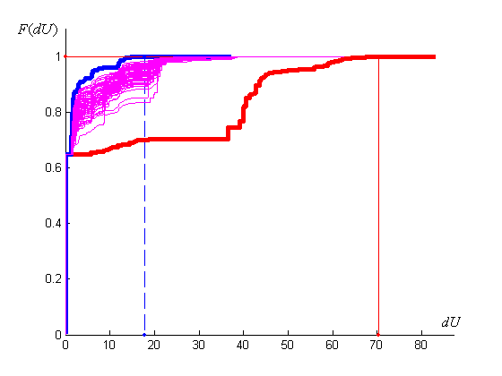
Figure 1 - Distribution functions of losses of line voltage AB for the first busbars: blue - low, red - maximum, violet - a method of "Random selection" (60 pieces)
In Fig. 2 and 3 shows the average distribution function at a different number of averaged functions.
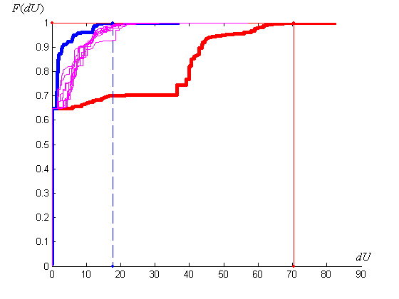
Figure 2 - Distribution functions of losses of line voltage AB for the first busbars: blue - minimum, red - maximum, violet - a method of "Multiple random selection" when the average number of distribution functions from 2 to 10
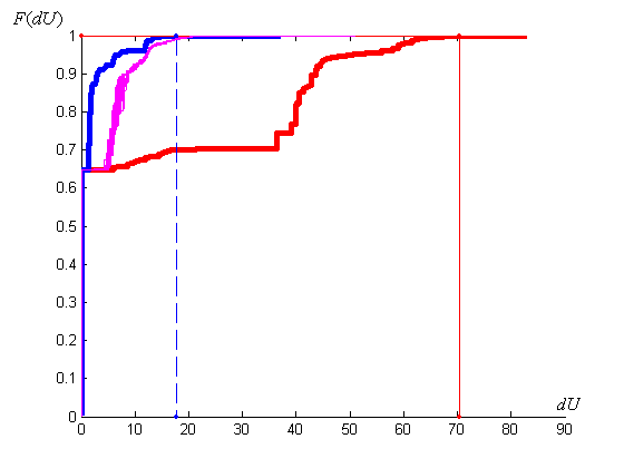
Figure 3 - Distribution functions of losses of line voltage AB for the first busbars: blue - minimum, red - maximum, violet - a method of "Multiple random selection" when the average number of distribution functions from 10 to 60
The results show that if the number of distribution functions averaged over 20, the resulting distribution function differ little from one another. The maximum calculated value of the loss of voltage, defined by them, does not change.
Then compare the results determine the maximum current value of the loss of line voltage AB, depending on the number of averaged results that were obtained by other methods.
")
Figure 4 – Сompare the results of the losses line voltage AB
3. The direction of future research
Further comparisons will perform distribution functions obtained by BVV with accurate (for relatively small groups of resistance welding machines) develop a new method for which will be carried out calculations of currents and voltages of all branches of the network at each step calculating the distribution functions of peak current and voltage losses. Improving the accuracy of this method is obtained by changing the separation the resistance welding machines in the group: to calculate the distribution function of each separate lot of groups will vary and implemented according impact of each the resistance welding machine on similar loss of voltage or peak current.
References
- Мешель Б.С. Применение математической статистики для определения электрических нагрузок промышленных предприятий. Энергосбыт Киевэнерго, Киев, 1958. – 128 c.
- Каялов Г.М. Определение расчетных нагрузок промышленных электрических сетей по методу упорядоченных диаграмм нагрузок // Материалы научно-технического совещания по определению электрических нагрузок и регулированию напряжения промышленных предприятий. Госэнергоатомиздат, 1958, вып.3. – C. 14–16.
- Руководящий технический материал. Указания по расчету электрических нагрузок: РТМ 36.18.32.4 – 92: Утв. ВНИПИ Тяжпромэлектропроект: Введен с 01.01.93 // Инструктивные и информационные материалы по проектированию электроустановок. – М.: ВНИПИ Тяжпромэлектропроект. – 1992. – № 6-7. – C. 4–27.
- Каялов Г.М. Принцип максимума средней нагрузки в расчетах электрических сетей. ИВУЗ, Электромеханика, 1964. – №3. – c.8–11.
- Вагин Г.Я. Исследование режимов работы и расчет пиковых нагрузок машин контактной электросварки. //Электрические сети и системы, Межведомственный республиканский научно-технический сборник, 1970, вып.7. – C. 8–10.
- Муха В.П. Вопросы теории и расчета электрических нагрузок и потерь напряжения в сетях контактной электросварки. // Диссертация на соискание ученой степени к.т.н. Ростовский-на-Дону институт инженеров железнодорожного транспорта, 1975. – 204 c.
- Каялов Г.М. Теоретические основы аналитического метода максимальных токов и потерь напряжения в сетях контактной электросварки / Г.М. Каялов, В.П. Муха, А.А. Бадахян, Л.Б. Годгельф // Инструктивные указания по проектированию электротехнических промышленных установок. – М.: ГПИ Тяжпромэлектропроект, 1976. - №3. - С. 3-9.
- Мукосеев Ю.Л., Вагин Г.Я., Червонный Е.М. Расчет суммарной нагрузки машин контактной сварки методом статистического моделирования на ЦВМ. // Электричество. 1972, – №6. – C. 1–9.
- Adams C., Fetcher J., Johnson A. The design of low-voltage welding power distribution // Tr. AIEE. - 1944. - v. 63 - p. 571-577.
- Adler H.A., Miller K.W., A new approach to probability problems in electrical engineering // Tr. AIEE. - 1946. - v. 65 - p. 630-632.
- Вагин Г.Я. Режимы электросварочных машин. – М.: Энергия, 1975. – 189 c.
- Воротніков С.О. Розрахунок напруг у електричній мережі, від якої живляться машини контактної зварки. Кваліфікаційна робота магістра – Донецьк, ДонНТУ, 2009. – 100 с.
- Болотнов Д.В. Розрахунок максимальних струмів і втрат напруги в електричних мережах живлення машин контактної електричної зварки. Кваліфікаційна робота магістра – Донецьк, ДонНТУ, 2010. – 100 с.
- Мухін В.В. Розрахунок пікових струмів і втрат напруги в електричній мережі живлення групи машин точкової контактної зварки. Кваліфікаційна робота магістра – Донецьк, ДонНТУ, 2012. – 89 с.