Control and orientation of the robot Koala indoors using optical flow (an onboard camera)
Авторы: Milan Zaitsev, Vyatcheslav Khomenko, Artem Melnik
Аннотация
Milan Zaitsev, Vyatcheslav Khomenko, Artem Melnik. Control and orientation of the robot Koala indoors using optical flow (an onboard camera). У статті розглядаються деякі способи керування поведінкою робота «Коала» («Ка-Тім», Швейцарія), використовуючи моделювання та з’єднання з комп’ютером для подальшого створення алгоритму вихідного оптичного потоку для орієнтації та уникання перешкод мобільним роботом у приміщенні.
Short description of the robot
Koala - the wheel mobile robot with the average size.
The robot is equipped by two blocks on three lateral wheels, with the maximum speed 0.4 m\s, wheels have the radius of 45 mm and are established on axes of the length 30 cm, control of which gives a possibility to change the rotation and the speed of the moving of the robot. So far as they are independent, the robot can turn on a place. Its mass is 3.6 kg (4 kg with the battery). Each engine is equipped by the incremental coding device, which is reading out 5850 pulsations for one turn. Koala has the processor Motorola 68331@22 MHz for control.
To operate the robot, it is possible to send commands from the personal computer via the serial port RS232, and the robot answers any action, or to send to data back (reading of coding devices). Engines can be operated directly, regulating a cycle of applied signal PWM of each engine, or indirectly through the enclosed controllers of position and speed. Koala is equipped by 16 infra-red sensors; each of them can measure surrounding brightness or proximity to the closest obstacle. But in the presented work infra-red sensors are not used and are replaced by the onboard camera that is working as an optical flow. Images from the camera are made through the graphic card connected with the personal computer. The control and visual algorithms are carried out, generally using language C ++.
In the project on an off-line control the wheel robot Koala in the environment of the closed premises and on open air, it is possible to develop visual perception with which the robot can move in a corridor at the expense of the automatic control as its speed and its free space to walls.
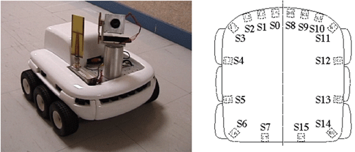
Figure 1 – Photo and scheme of the robot Koala (Source: [3])
The digital onboard camera FireWire is the most preferable to the further work, corresponding to the specification IIDC for industrial not compressed VGA of reception of the image, created on the basis of the chipset of the digital camera Texas Instruments 1394 and PZS-SENSOR CONTROLS Sony ® Wfine Fire-i™ (fig. 2).
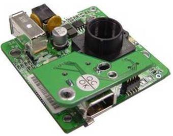
Figure 2 – The digital camera Fire-i™
The equation of optical flow
Optical flow is a field of visual moving which allows to explain changes of one image to another in the fonction of moving of the points. The hypothesis which becomes from this is to take the simple equation, that a colour of a point of the image is independent of time.
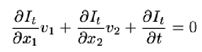
This equation doesn’t allow to define an optical flow as uniqually because in each point of the image we do not have that unique scalar compulsion to define a vector of two coefficients (v1, v2).
So, in the form: Ixu+Iyv+It=0,
- Ix, Iy and It – spatio-temporal derivatives of the image brightness;
- u – a horizontal optical flow;
- v – a vertical optical flow.
For calculating the optical view field of two successive camera images (estimating the direction and speed of object motion from one image to another or from one video frame to another), we can use an optical flow algorithm of Horn and Schunk or Lucas-Kanade. These methods have the main difference: the first one is more exact but slower, the second one is faster but it has light precision.
So for example let’s examine Lucas-Kanade Method as it is a bit easier in my opinion.
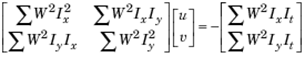
To solve the optical flow constraint equation for u and v, the Lucas-Kanade method divides the original image into smaller sections and assumes a constant velocity in each section. Then, it performs a weighted least-square fit of the optical flow constraint equation to a constant model for [u v]T in each section, by minimizing the following equation:
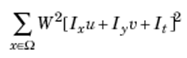
Here, W is a window function that emphasizes the constraints at the center of each section. The solution to the minimization problem is given by the following equation:
For making some visualization we have used the Matlab demo “Tracking Cars Using Optical Flow”. This demo uses Video and Image Processing Blockset™ blocks to illustrate how to detect and track cars in a video sequence using optical flow estimation (fig. 3). This model uses an optical flow estimation technique to estimate the motion vectors in each frame of the video sequence. By thresholding and performing morphological closing on the motion vectors, the model produces binary feature images. The model locates the cars in each binary feature image using the Blob Analysis block. Then it uses the Draw Shapes block to draw a green rectangle around the cars that pass beneath the white line. The counter in the upper left corner of the Results window tracks the number of cars in the region of interest.
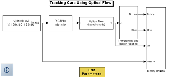
Figure 3 – Tracking Cars Using Optical Flow model
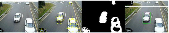
Figure 4 – Images that determine changing evoked by moving of the cars
Based on this optical flow field, the flow magnitudes of right and left half of each image is calculated. If the sum of the flow magnitudes of the view reaches a certain threshold, it is assumed there is an obstacle in front of the robot. Then the computed flow magnitude of right and left half image is used to formulate a balance strategy: if the right flow is larger than the left flow, the robot turns left - otherwise it turns right.
![Figure 5 – The robot Koala block diagram (Source: [1])](images/article1_pic8.png)
Figure 5 – The robot Koala block diagram (Source: [1])
For the purpose of acquaintance with the control of the robot Koala in the environment of Matlab, the basic functions and commands have been used for the regulation of speed, position, acceleration of the engines of the wheels. The establishment of communication of the robot and the computer was made using the standard interface RS232.
As a result we have received the diagram of actuating of the wheels (blue – left and green – right ones) with various values of speed and time of the acceleration on each of them. The reaction to the additional resistance to movement applied to one of wheels is shown also on the diagram.
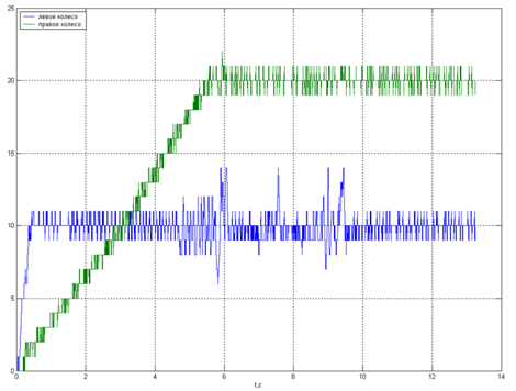
Figure 6 – Acceleration of wheel engines of the robot
Conclusion
Control of robots by means of optical flow is an interesting sphere in autotechnique and robotics thanks to the presentation of managerial process for the user, besides there is a possibility of elaboration, modelling and adjustment in several programs (Matlab, Webots, LabView) besides using an integral chip. The basic understanding of using the optic flow and control of Koala allows hereafter to develop more specific operations with the digital camera.
Bibliography
1. 1. Alaa DIB. «Commande non lineaire et asservissementvisuel de robots autonomes», – These de doctorat de l’ecole doctorale “Sciences et Technologie de l’infirmation des Telecommunications et des Systemes”. 2011, page 155.
2. K-Team S.A. «Koala User Manual», – Lausanne, Version 1.1. 1999.
3. Сайт компании «K–team». http://www.k–team.com/