LedRangeFinder – User Manual
Documentation Author
Arnaud Maye (K-Team S.A.)
Ch. du Vuasset, CP 111
1028 Preverenges
Switzerland
Trademark Acknowledgments:
IBM PC: International Business Machine Corp.
Macintosh: Apple Corp.
SUN Sparc-Station: SUN Microsystems Corp.
Koala: K-Team and LAMI
1 Introduction
1.0.1 LedRangeFinder
The LedRangeFinder board is an extension that provides necessary hard-ware to use the Hokuyo PBS-03JN module on the K-Team Koala robot. Even if this board may be used with an external desktop personnal computer, we recommend to use the KoreBot cpu board with the KoreBotAdaptor board.
1.0.2 PBS Module
The Infrared Scanner module allows to instant reliable measurement of the whole front 180 degrees, this even if one can retrieve from 18 deg minus to 198 deg. Measurement principle of this module isn’t known. Only things that are known is that internal leds are rotating at a 600 turns per minute rate while measuring reflected light with an 1.8 degree resolution. Every received measure block will gives more than hundred millimeters values. The module delivers tens measures per minute, but we recommend to average several measurements to increase the reliabilty of the results.
1.0.3 PBS Communication
The Infrared Scanner module using some system to ensure that the software has been compiled for the specific module.
Note that programmer doesn’t requires to deal with such low level func- tions for a normal situation, because top level apies doing the whole link certification.
2 Led Range Finder Hardware
2.1 Overview
LedRangeFinder.
Figure 2.1 describes the board main components.
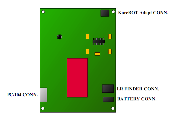
Figure 2.1: LedRangeFinder hardware overview
2.2 LedRangeFinder Connections
2.2.1 Communication Connections
LedRangeFinder offers two communication connectors.
The ’PC/104’ connector is used as a RS232 input (+/-9V min), because
its type, is starightforward to build your own cable to plug your own desktop
computer. However, best results are achieved via the KoreBOT adaptor
connector.
The ’KoreBOT adaptor’ connector is used as main communication chan-
nel. DO NOT CONNECT the KoreBOT without to use the KoreBOT adpator, that would just damage your Korebot.
The ’LR Finder’ connector is used to connect the PBS-03JN module
2.2.2 Power Connections
The LedRangeFinder card is powered by the KoreBot via the KoreBot Adaptor board.
The BATTERY connector is used to power the DC/DC converter which
will requires at least 9V dc to function properly. Be attentive that wire
should resist to about 1A. This because the on-board fuse is 1A as well
2.3 Hardware Protection
2.3.1 Electrostatic Discharge Protection
As any electronic device, the KoreSound may be damaged by Electrostatic Discharge.
3 LedRangeFinder Software
3.1 Overview
This chapter presents how to use LedRangeFinder from a KoreBot ( with a
KoreBot Adpator ) using a Linux Operating System. It requires:
• a KoreBot (with a KoreBot Adpator)
• a LedRangeFinder
• a terminal emulator software (such as minicom or HyperTerminal)
• a host computer with at least one RS-232 connector (such as a standard
PC running Linux or Windows)
• GNU tools for KoreBot (assembler, linker and C/C++ compiler for Intel XScale processor) running on your host computer (only for programming lrf application)
3.2 LedRangeFinder Programming on KoreBot
This section shows how to access to the led reange ?nder from your stan- dard Linux application. The examples given are in standard C and use the standard C library. It requires some knowledge about the ?le functions on Linux.
3.2.1 simple LRF programming
There is no need to load a particular driver, what you requires is to use the
prede?ned APIs provided with the standard korebot library. Start with to
add korebot header to your source code. And then initialise the led range
?nder module.
#include
int LRF_DeviceHandle; /* Handle to the device */
LRF_DeviceHandle = kb_lrf_Init();
if kb lrf init returns with a negative value, there was an issue. So if
LRF Device Handle isn’t negative, we can continue with retrieving some
values from the LRF. For the example, let’s loop 10 times while retrieving and printing out measurement. We ?nishing with closing the led range
?nder module This is the simplest possibled software code and the usage of
kb lrf distancedata gives averaged results.
the measure is stored in an array called kb lrf DistanceData that is de-
?ned as an external variable within the kb lrf software.
if (LRF_DeviceHandle > 0)
{
for (int i=0; i<10; i++)
{
if (kb_lrf_GetDistances(LRF_DeviceHandle) >= 0)
{
for (int j=0; j<121; j++)
{
printf ("Dir %3.3d: ", j);
printf ("%6.6d ", kb_lrf_DistanceData[j]);
}
}
printf("\n");
}
kb_lrf_Close(LRF_DeviceHandle);
}
3.2.2 advanced LRF programming
Of course, there is more APIs available for programmers. Especialy because the led range ?nder module requires much power programmer may
use kb lrf pwrO? to turn o? the on board DC/DC converter which just
turn down the module. Note that the kb lrf init function does calling
kb lrf pwrOn and that kb lrf close function does calling kb lrf pwrOff
A simple measure that turns on, get ?ve measures and turns o? the
module.
int getMeasure( unsigned char[][] * ptr )
{
int rc = -1; /* variable for return code */
int LRF_DeviceHandle; /* Handle to the device */
LRF_DeviceHandle = kb_lrf_Init();
if (LRF_DeviceHandle > 0)
{
for (int i=0; i<10; i++)
{
if (kb_lrf_GetDistances(LRF_DeviceHandle) >= 0)
{
memcpy(ptr[i][0], kb\_lrf\_DistanceData, 121);
}
}
rc = 0; /* success */
kb_lrf_Close(LRF_DeviceHandle);
}
return rc;
}
}
We encourage programmers to check the kb lrf.c from the libkorebot’s
src folder to get more infos about the other api.
3.2.3 Supported LRF APIs
We encourage programmers to check the kb lrf.c from the libkorebot’s src folder to get more infos about the apies.