
Abstract
Contents
- Introduction
- 1. Urgency
- 2. Analysis of existing designs slag
- 2.1 Slag screw mechanism for tilting the bowl
- 2.2 A gear mechanism for tilting the bowl slag
- 3. Description of the proposed construction of a four-bowl tilting mechanism slag
- Conclusion
- References
Introduction
BOF steel production, at present, is one of the leaders, because it allows you to quickly melt the pig iron in a high-quality steel. The process of steel production is accompanied by the release of by-products, one of which is slag. Many large steel mills recycling slag reaches 70÷80% or more. At present, posed and solved the problem of processing of metallurgical slag in the construction industry suitable for the product and the complete elimination of the territory of the plant slag dumps. The basic amount of slag is granulated, some of the recycle on the gravel, pumice, shlakolitye products, mineral wool, mineral fertilizers. Granulation is carried out at some distance from the stove or plant [1].
To clean the slag from the furnace and transporting it to recycling or dumping slag is used. To slag impose the following basic requirements: a form of bowls should help smooth out of it solidified slag on the slag heap, should be excluded the possibility of spontaneous breaking the bowl as if it tilting, and when moving or stopped, slag, should be provided with lateral stability slag at overturning the bowl both laden and unladen, design, shape and material of the cup, as well as a way of fixing must ensure a high durability of the cup, the drive mechanism for tilting should be empowered to adjust the speed of discharge of slag granulation plants [1].
Therefore, it was designed and investigated with the help of modern technology – crank mechanism slag tipping the bowl. Also investigated was the process of tilting the bowl, namely, the nature of the change in the moment of resistance tilting bowl.
1. Urgency
Smelters are among the major economic projects, to a large extent determine the level of economic development. Of the variety of man-made structures, obtained in the steel industry, the bulk (80%) of the total amount of industrial solid waste (TPO) are slag heaps. Recycling of wastes determines the practical nature of the organization of metallurgical production waste-free.
Located in the city landscape of slag heaps violate the territories to accommodate dumps of alienated land, deteriorating environmental situation in the region.
Currently, in most developed countries the use of silicate production of metallurgical enterprises reaches 90%. In the construction industry used their astringent properties. However, the most valuable thing in the slag is a metal. Methods of extracting metals from liquid waste, proven in industrial environments, no. Therefore, the metal is removed only at the enterprises of the solid residues in the primary treatment for the installation of granular and secondary - for crushing and screening plants.
Existing at a given time arrangements slag tipping the bowl, can not provide uniform merging granulated slag on plants for slag granules from the same faction for the convenience of processing in the crushing plants.
Faced with this question, the answer was found in the study and construction of a physical model of the crank-connecting rod mechanism of tilting, which ensures even draining granular slag on the setting that provides more efficient processing of slag with less.
2. Analysis of existing designs slag
At present, enterprises of metallurgical complex, exploiting the different slag not only by the amount of cups, but the design of tilting mechanisms.
2.1 Slag screw mechanism for tilting the bowl
The screw mechanism of tilting the bowl (Fig. 2.1.), Mounted on the frame, comprises: an electric motor 14 VAC, single-stage spur gear 13, intermediate shaft connected to the gearbox and clutch bearing the gear 12, a pair of meshing with each other identical spur gears 11, one of which receives the rotation of the pinion 12, and two parallel, mounted on ball bearings loading screw 10 with self-locking acme screw, two screws 9, set out in the boom 8, which is freely mounted (on sleeve) in one of the 6 pins of the support ring. Gear wheels 12 and 11 are closed casing.
Through a system of rotation of the gear motor 14 is converted by screws 10 to the forward movement of the screws 9 and traverses 8, and hence the support ring with the cup. Being engaged with the fixed rails 3, 5 gear sectors in this run-in on them, causing the rotation of the support ring with the cup.
Thus, the motion of the guide rollers 7 to 4 is tipping the bowl while you move it from the middle of the slag to the edge of the frame. As we approach the cup to the edge of the frame, the angle of rotation of the cup increases reaching 116÷118° for 1,3÷1,5 s. Tipping can be done in both directions. Turn off the motor when dostizhenizhenii cup extreme positions of controller 1 is connected with the lower screw 10 through the worm gear kinematichnoy 2. The above mechanism has a lifetime of small screws and nuts due to the harsh conditions of their work [2].
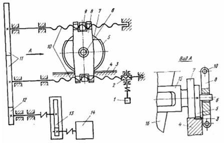
Figure 2.1 – Kinematic screw mechanism tilting bowl slag
2.2 A gear mechanism for tilting the bowl slag
In this type of slag structure is tilting the bowl through the gears (see Figure 2.2.). From a flanged motor through a self-locking gear 2 to gear console 10 transmit rotation of the toothed sector 3, which is clearly attached to a pin of the support ring 7 4 cup. Sector 3 and the support ring with another toothed sector 5, performed with the roller 6 is moved by obkatyvaniya sector 5 and 6 fixed roller and smooth gear segments 11 which are mounted on the rack carriage 13. At the same time ensure the movement of the support ring with the cup in a direction perpendicular to the axis of the railway line and turn the bowl at an angle of up to 118°.
The constancy of center distance between the axis of the output shaft gear 2 and the axis of the trunnion 7 support ring 4 is provided with tilting planet carrier 12 which are mounted on trunnions 7 support ring 4 and 14 are connected to the axle carriage 13 [2].
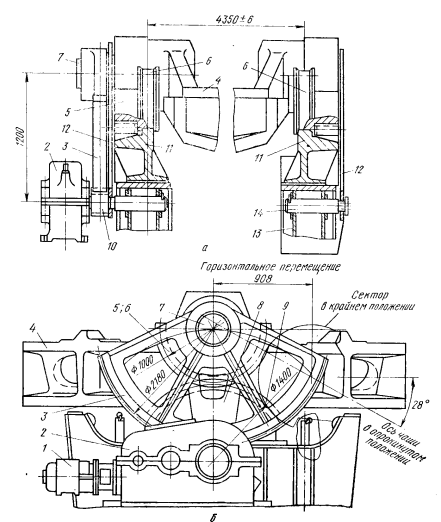
Figure 2.2 – A gear tilting mechanism of slag bowl
3. Description of the proposed construction of a four-bowl tilting mechanism slag
Kinematic scheme a four-bowl tilting mechanism slag is shown in Figure 3.1. From a gear motor torque is transmitted to the crank 2, which is rigidly fixed to the output shaft of the geared motor. Crank 2 via the connecting rod 3 transmits the force on the lever 4, which is rigidly secured to the trunnion cup slag. In consequence of turning the lever 4 is tilting bowl, with the bowl is moved a certain distance perpendicular to the railroad tracks. When tilting the bowl gear 5 and roller 6 which is rigidly fixed to trunnion cups, rail travel, respectively, 7 and Track 8, which are mounted on the frame slag. It should be noted that the full back of the crank 2 is a complete cycle of tilting the bowl, but as tilting and return the bowl to its original position.
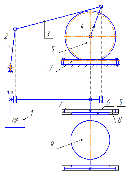
Figure 3.1 – Kinematic scheme a four-bowl tilting mechanism slag
Conclusion
In this master's work, using mathematical modeling was carried out reconstruction of the mechanism for tilting the bowl shlakovoznoy carts, with electro-mechanical drive. Kinematic study of the mechanism possible to find dependence of the angular velocities, velocities and accelerations, the links point mechanism, dependent on the angle of rotation of the crank. The same was calculated moment of resistance when tilting the bowl slag.
In writing this essay master's work has not yet been completed. Final completion: January 31, 2013. The full text of the work and materials on the topic can be obtained from the author or his head after that date.
References
- Машины и агрегаты металлургических заводов: В 3 т. /А.И. Целиков, П.И. Полухин, В.М. Гребенник и др. Т.1. – М.: Металлургия, 1987. – 440 с.
- Механическое оборудование металлургических заводов. Механическое оборудование фабрик окускования и доменных цехов. В.М. Гребенник, Д.А. Сторожик, Л.А. Демьянец и др. – К.: Вища шк. Головное изд-во, 1985. – 312 с.
- Расчет металлургических машин и механизмов / В.М. Гребенник, Ф.К. Иванченко, В.И. Ширяев – К.: Вища шк. Головное изд-во, 1988. – 448 с.
- Расчеты грузоподъёмных и транспортирующих машин. Учебник для вузов / Ф.К. Иванченко, В.С. Бондарёв, Н.П. Колесник, В.Я. Барабанов. – 2-е изд., перераб. и доп. – Киев.: Высшая школа, 1978. – 576 с.
- Попов С.А., Тимофеев Г.А. / Курсовое проектирование по теории механизмов и механике машин. – М.: Высшая школа, 1999. – 351 с.