
Abstract
Contents
- 1. The relevance of the work
- 2. The objective of this work
- 3. Research tasks
- 4. The main contents of the work
- Conclusion
- References
1. The relevance of the work
A mine drag conveyer is the main means of transportation of the mined rock and of delivery of the functional units of technological equipment in a stope of a coal mine. Characteristic features of its drive construction (the use of a non speed-adjustable induction motor with a short circuited rotor and a hydrolic clutch) cause a high intensity acceleration of a drag chain (with a jerk in the setting in motion) and a haulage operations’ performance at a high (nominal) speed. All this constitutes a staff`s injury hazard and requires the improvement of the drag conveyer drive`s design.
The effective technical solution of this problem is the use of two-speed induction motors with synchronous speeds 1500 revo rotation pre minute and 500 revo rotation per minute. However, the peculiarity of their exploitation consists in the fact, that when the engine is in operation, an induced electromotive force is being created in its disconnected motor winding. It represents an electrical shock hazard.
Taking into account that the overall tests regarding an electrical shock factor of the induced electromotive force in the disconnected motor winding, while the engine of EKDVF type is in operation, have not been carried out, the study of operation factors of the induced electromotive forces in disconnected motor windings of two-speed engines in the context of the probability of the people`s electrocution, represents scientific and practical relevance.
2. The objective of this work
The aim of this work is to enhance the safety of a two-speed induction motor operation when it forms a part of the electrical drive in a mine drag conveyer. The improvement can be achieved based on a study of an electrocution function of the induced electromotive force in a disconnected motor winding and on a structure justification of the technical means providing an electrical service safety.
3. Research tasks:
- To perform an analytical review of the problems regarding construction and operation of electrical systems of technological mine areas, including ways and means to protect people from electrocution.
- To develop and explore a mathematical model of the electrical complex of a mine unit, considering the parameters of the induced electromotive forces in the disconnected motor winding of a two-speed induction motor.
- To justify the structure and parameters of the technical means to guarantee a safety of the operation of two-speed motors in mine conditions.
- To develop a basic scheme, providing an electrical safety of a two-speed motor in operation and draw out operating requirements for a mine unit.
4. The main contents of the work
The particular characteristic of a modern electrical complex of a mine unit is a widespread use of two-speed motors. The main object where these motors are being used is a mine drag conveyer.
The haulage operations are performed at a nominal speed, which directly depends on a type of a mine drag conveyer and fluctuates within 1,08–1,2 meters per second. In this regard a compulsory use of a haulage speed has been set by current standards concerning drag conveyers` drives.
A construction of such motors provides two stator windings with different number of pole pairs ( for example, 4 and 12) (figure 1)[1, 2]. Depending on the kind of a stator winding which is in operation, a motor can produce a synchronous speed of 1500 and 500 rev/min [3]. A scheme of a two-speed induction motor electrical power supply (figure 2).

Figure 1 – A construction of a two-speed induction motor of EDKVF type.

Figure 2 – A scheme of a two-speed induction motor electrical power supply
The presence of two stator windings produces prerequisites for a transformer effect, emerging when one of the windings is connected. It produces potentially hazardous conditions.
Under the conditions of laboratory bench parameters of the induced electromotive force in the disconnected stator winding while the other stator winding is connected (figure 3), have been revealed [4].
 and of a <q>nominal rate (b)</q>")
Figure 3 – Oscillograms of the induced electromotive force of a two-speed induction motor`s stator on non-connected windings of a reduced speed
(a) and of a nominal rate
(b)
Consider the situation when the drag conveyer operates at a nominal rate. The type of a cable accepted is KGESH with a cross-section 25–70 sq mm and with a length of 10–300 m [5]. Its active insulation resistance is 100 k ohm/per phase, 50 k ohm/per phase and 31 k ohm/pre phase.
Based on the analysis of the induced electromotive force`s form, compose a computer model. Take an active resistance of an electrical leak equal to 1 k ohm [6]. A structural diagram of the computer model is represented in figure 4.
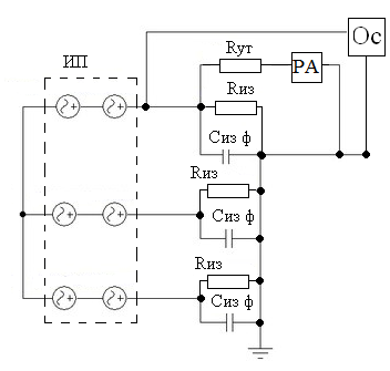
Figure 4 – A structural diagram of the computer model, studying an electrical leak to the ground in the disconnected winding with a reduced speed of a two-speed induction motor: where PA is an ammeter, Oc - is an oscilloscope, IP are appropriate supply sources, Ryt - is an active insulation resistance, Siz F - is an insulation capacity per phase
As a result of processes` modeling in a disconnected joining of a two-speed induction motor, an oscillogragh chart has been obtained. It represents the induced electromotive force in a stator winding (figure 5).

Figure 5 – An extract of the oscillograph chart obtained with the help of a virtual oscilloscope
Simulation results are being summarized in a graph (figure 6).

Figure 6 – A resultant graph of an electrical leak
Conclusion
The evaluation of the simulation results allows to come to a conclusion regarding a danger of the electrocution in a case when a person touches a winding phase of an induction motor (figure 7).

Figure 7 – Danger of the electrocution in a case when a person touches a winding phase of an induction motor
(animation: 15 frames, 5 cycles of repeating, 168 kilobytes)
References
- Номенклатурный справочник продукции АО «Первомайский электромеханический завод имени Карла Маркса». – Донецк, 2003.
- Электродвигатель асинхронный типа ЭКВФ355L12/4. Руководство по эксплуатации ВГИЕ. 526726.002 РЭ.
- Автоматизація технологічних об’єктів та процесів. Пошук молодих. Збірник наукових праць ХІ науково-технічної конференції аспірантів та студентів в м. Донецьку 17–20 травня 2011 р. – Донецьк, ДонНТУ, 2011. – 306 с. Статья Мартынюк Л.В., студент; Маренич К.Н. Моделирование обратных энергетических потоков в отключенной обмотке статора двухскоростного двигателя с целью совершенствования защиты от утечек тока на землю.
- К.М. Маренич, Ю.В. Товстик, В.В. Турупалов, С.В. Василець, І.Я. Лізан. Автоматизований електропривод машин і установок шахт і рудників: навч. посібник для вузів / Під загальною редакцією К.М. Маренича. – Донецьк: ДонНТУ, Харків: УІПА, 2011. – 244 с.
- Автоматизація технологічних об’єктів та процесів. Пошук молодих. Збірник наукових праць ХІІ науково-технічної конференції аспірантів та студентів в м. Донецьку 17–20 травня 2012 р. – Донецьк, ДонНТУ, 2012. – 300 с. Статья Мартынюк Л.В., студент; Маренич К.Н. Исследование возможности электропоражающего фактора отключенной обмотки двухскоростного асинхронного двигателя при его эксплуатации в шахтной электросети.
- Аппараты защиты от токов утечки рудничные для сетей до 1200 В. Общие технические условия. ГОСТ 22929-78, 16 с.