One of the key factors for the successful deployment of mobile satellite systems in 4G networks is the maximization of the technology commonalities with the terrestrial systems. An effective way of achieving this objective consists in considering the terrestrial radio interface as the baseline for the satellite radio interface. Since the 3GPP Long Term Evolution (LTE) standard
will be one of the main players in the 4G scenario, along with other emerging technologies, such as mobile WiMAX; this paper analyzes the possible applicability of the 3GPP LTE interface to satellite transmission, presenting several enabling techniques for this adaptation. In particular, we propose the introduction of an inter-TTI interleaving technique that exploits the existing H-ARQ facilities provided by the LTE physical layer, the use of PAPR reduction techniques to increase the resilience of the OFDM waveform to non linear distortion, and the design of the sequences for Random Access, taking into account the requirements deriving from the large round trip times. The outcomes of this analysis show that, with the required proposed enablers, it is possible to reuse the existing terrestrial air interface to transmit over the satellite link.
Copyright © 2009 Francesco Bastia et al. This is an open access article distributed under the Creative Commons Attribution License, which permits unrestricted use, distribution, and reproduction in any medium, provided the original work is properly
cited.
1. Introduction and Motivation
Integrated terrestrial and satellite communication system is
a paradigm that has been addressed for many years and that
is at the fore front of the research and development activity
within the satellite community. The recent development of
the DVB-SH standard [1] for mobile broadcasting demonstrates
that virtuous synergies can be introduced when terrestrial
networks are complemented with a satellite component
able to extend their service and coverage capabilities. A
key aspect for the successful integration of the satellite and
terrestrial components is the maximization of technological
commonalities aimed at the exploitation of the economy of
scale that derives from the vast market basis achievable by
the integrated system. In order to replicate in 4G networks
the success of the integrated mobile broadcasting systems,
many initiatives are being carried out [2, 3] for the design
of a satellite air interface that maximizes the commonalities
with the 4G terrestrial air interface. These initiatives aim
at introducing only those modifications that are strictly
needed to deal with the satellite channel peculiarities,
such, for example, nonlinear distortion introduced by the
on-board power amplifiers, long round-trip propagation
times, and reduced time diversity, while keeping everything
else untouched. Specifically, it is important to highlight
the different mobile channel propagation models between
terrestrial and satellite environments. In fact, in terrestrial
deployments, channel fades are typically both time and
frequency selective, and are counteracted by the use of
opportunistic scheduling solutions, which select for each
user the time slots and the frequency bands where good
channel conditions are experienced. On the other hand,
satellite links are characterized by large round trip delay,
which hinders the timeliness of the channel quality indicators
and sounding signals, continuously exchanged between users
and terrestrial base stations. Further, satellite channel fades
are typically frequency-flat, due to the almost Line-of-Sight
(LOS) nature of propagation in open area environments,
thus alternative solutions have to be designed in order to
increase the satellite link reliability.
In this framework, this paper investigates the adaptability
of the 3GPP Long Term Evolution (LTE) standard [4] to the
satellite scenarios. The 3GPP LTE standard is in fact gaining
momentum and it is easily predictable to be one of the
main players in the 4G scenario, along with other emerging
technologies such as mobile WiMAX [5]. Thanks to this
analysis, we propose the introduction of few technology
enablers that allow the LTE air interface to be used on a
satellite channel. In particular, we propose the following:
(i) an inter-TTI (Transmission Time Interval) interleaving
technique that is able to break the channel
correlation in slowly varying channels by exploiting
the existing H-ARQ facilities provided by the LTE
physical layer;
(ii) the introduction of PAPR reduction techniques to
increase the resilience of the OFDM waveform to
nonlinear distortions;
(iii) a specific design of the sequences for the random
access scheme, taking into account the requirements
deriving from large satellite round trip times.
In addition, with the aim of further enhancing the robustness
to long channel fades, an Upper-Layer (UL) Forward Error
Correction (FEC) technique is also proposed and compared
with the inter-TTI technique.
According to market and business analysis [6], two
application scenarios are considered: mobile broadcasting
using linguistic beams with national coverage and two-way
communications using multispot coverage with frequency
reuse. Clearly, the service typologies paired with these two
application scenarios have different requirements in terms of
data rates, tolerable latency, and QoS. This has been taken
into account into the air interface analysis.
2. GPP LTE:Main Features
The 3GPP LTE air interface is shortly summarized to ensure
self-containment and to provide the perspective for the
introduction of advanced solutions for the adaptation to
satellite links, as described in Section 3.
The FEC technique adopted by LTE for processing
the information data is a Turbo scheme using Parallel
Concatenated Convolutional Code (PCCC) [7]. Two 8-state
constituent encoders are foreseen and the resulting coding
rate is 1/3. The LTE technical specifications provide several
values for the input block size KTC to the Turbo encoder,
varying form KTC = 40 up to KTC = 6144. After channel
encoding, the Circular Buffer (CB) and Rate Matching (RM)
block allows to interleave, collect and select the three input
streams coming from the Turbo encoder (systematic bits,
parity sequence from encoder-1 and encoder-2), as depicted
in Figure 1. The three input streams are processed with the
following steps.
(1) Each of the three streams is interleaved separately by
a sub-block interleaver.
(2) The interleaved systematic bits are written into the
buffer in sequence, with the first bit of the interleaved
systematic bit stream at the beginning of the buffer.
(3) The interleaved P1 and P2 streams are interlaced
bit by bit. The interleaved and interlaced parity bit
streams are written into the buffer in sequence, with
the first bit of the stream next to the last bit of the
interleaved systematic bit stream.
(4) Eight different Redundancy Versions (RVs) are
defined, each of which specifies a starting bit index in
the buffer. The transmitter reads a block of coded bits
from the buffer, starting from the bit index specified
by a chosen RV. For a desired code rate of operation,
the number of coded bits Ndata to be selected for
transmission is calculated and passed to the RM
block as an input. If the end of the buffer is reached
and more coded bits are needed for transmission,
the transmitter wraps around and continues at the
beginning of the buffer, hence the term of “circular
buffer.” Therefore, puncturing, and repetition can be
achieved using a single method.
The CB has an advantage in flexibility (in code rates
achieved) and also granularity (in stream sizes). In LTE, the
encoded and interleaved bits after the RM block are mapped
into OFDM symbols. The time unit for arranging the rate
matched bits is the Transmission Time Interval (TTI).
Throughout all LTE specifications, the size of various
fields in the time domain is expressed as a number of time
units, Ts = 1/(15000 x 2048) seconds. Both downlink and
uplink transmissions are organized into radio frames with
duration Tf = 307200Ts = 10 ms. In the following, the
Type-1 frame structure, applicable to both FDD and TDD
interface, is considered. Each radio frame consists of 20 slots
of length Tslot = 15360Ts = 0.5 ms, numbered from 0 to 19.
A sub-frame is defined as two consecutive slots, where subframe
i consists of slots 2i and 2i + 1. A TTI corresponds to
one sub-frame.
In general, the baseband signal representing a downlink
physical channel is built through the following steps:
(i) scrambling of coded bits in each of the code words to
be transmitted on a physical channel;
(ii) modulation of scrambled bits to generate complexvalued
modulation symbols;
iii) mapping of the complex-valued modulation symbols
onto one or several transmission layers;
(iv) pre-coding of the complex-valued modulation symbols
on each layer for transmission on the antenna
ports;
(v) mapping of complex-valued modulation symbols for
each antenna port to resource elements;
(vi) generation of complex-valued time-domain OFDM
signal for each antenna port.
These operations are depicted and summarized in Figure 2.
The details and implementation aspects of each block can
be extracted from [4]. The transmitted signal in each slot is
mapped onto a resource grid of Na active subcarriers (frequency
domain) and Nsymb OFDM symbols (time domain).
The number of OFDM symbols in a slot, Nsymb, depends on the cyclic prefix length, Ncp, and the subcarrier spacing, Δf.
In case of multiantenna transmission, there is one resource
grid defined per antenna port.

Figure 1: Rate matching and Virtual Circular Buffer.
The size of the FFT/IFFT block, NFFT, is equal to 2048 for Δf = 15 kHz and 4096
for Δf = 7.5 kHz. Finally, the time continuous signal of the
generic l-th OFDM symbol on the antenna port p can be written as
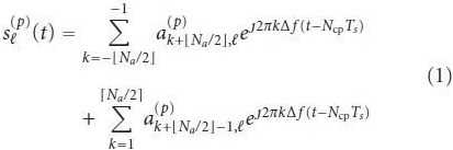
for 0 ≤ t ≤ (Ncp + NFFT)Ts
3. Adapting LTE to Satellite Links: Enablers
In the following sections, we propose and analyze some
solutions to adapt the 3GPP LTE air interface to broadband
satellite networks. These advanced techniques are applied
to the transmitter or receiver side in order to enhance
and maximize the system capacity in a mobile satellite
environment.
3.1. Inter-TTI Interleaving. In this section, we propose an
inter-TTI interleaving technique allowing to break channel
correlation in slowly varying channels, achieved through the
reuse of existing H-ARQ facilities provided by the physical
layer of the LTE standard [8].
The LTE standard does not foresee time interleaving
techniques outside a TTI [7]. Thus, since the physical layer
codeword is mapped into one TTI, the maximum time
diversity exploitable by the Turbo decoder is limited to
one TTI (TTTI). For low to medium terminal speeds, the
channel coherence time is larger than TTTI, thus fading events
cannot be counteracted by physical layer channel coding. In
order to cope with such a fading events, LTE exploits both
“intelligent” scheduling algorithms based on the knowledge
of channel coefficients both in the time and in the frequency
dimension, and H-ARQ techniques. The former technique
consists in exploiting the channel state information (CSI) in
order to map data into sub-carriers characterized by high
signal to noise ratio (good channel quality). Of course this
technique shows great benefits when frequency diversity is
present within the active subcarriers.
H-ARQ consists in the “cooperation” between FEC and
ARQ protocols. In LTE, H-ARQ operation is performed by
exploiting the virtual circular buffer described in Section
2. Orthogonal retransmissions can be obtained by setting
the RV number in each retransmission, thus transmitting
different patterns of bits within the same circular buffer.
Of course, H-ARQ technique yields to great performance
improvement when time correlation is present because
retransmission can have a time separation greater than
channel coherence time.
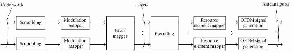
Figure 2: Overview of physical channel processing [4].
Unfortunately, neither of the aforementioned techniques
can be directly applied to the satellite case due to the
exceedingly large transmission delays, affecting both the
reliability of the channel quality indicators and of the
acknowledgements. Nevertheless, it is possible to devise
a way to exploit the existing H-ARQ facilities adapting
them to the satellite use. To this aim, we propose a novel
forced retransmission technique, which basically consists in
transmitting the bits carried in the same circular buffer
within several TTIs, that acts as an inter-TTI interleaving. To
do this, we can exploit the same mechanism as provided by
the LTE technical specifications for the H-ARQ operations
with circular buffer. For the explanation of this solution, the
block diagram depicted in Figure 1 can be taken as reference.
In this example, 4 retransmissions are obtained by using
4 different RVs, starting from 0 up to 3. Each of the 4
transmission bursts is mapped into different TTIs, spaced by
KTTI ·TTTI. KTTI is a key parameter because it determines the
interleaving depth and it should be set according to channel
conditions and latency requirements.
It is straightforward to derive the maximum time
diversity achievable by adopting such as technique. Let RTTI
be the number of retransmissions needed to complete the
transmission of a single circular buffer, LSUB the number
of OFDM symbols transmitted in each retransmission, and
TSUB the duration of LSUB OFDM symbols. (The duration
of the OFDM symbol TOFDM is intended to be the sum of
the useful symbol and cyclic prefix duration.) We have that
a codeword is spread over total protection time TTPT =
KTTI · (RTTI-1)·TTTI+TTTI. Given the fact that the standard
facilities are used, no additional complexity is introduced.
The drawback involved with the use of such technique is
the data rate reduction, brought about by the fact that one
codeword is not transmitted in TTTI but in TTPT. A possible
way to maintain the original data rate is to introduce in
the terminals the capability of storing larger quantities of
data, equivalent to the possibility to support multiple HARQ
processes in terminals designed for terrestrial use. In
this way, capacity and memory occupation grow linearly with
the number of supported equivalent H-ARQ processes, and
is upper bounded by the data rate of the original link without
inter-TTI.
3.2. PAPR Reduction Techniques.The tails in Peak-to-
Average Power Ratio (PAPR) distribution for OFDM signals
are very significant, and this implies an detrimental source
of distortion in a satellite scenario, where the on-board
amplifier is driven near saturation. To have an idea of the
cumulative distribution of PAPR, a Gaussian approximation
can be used. With this approach, if OFDM symbols in
time domain are assumed to be Gaussian distributed, their
envelope can be modeled with a Rayleigh distribution. Thus,
the cumulative distribution function of PAPR variable is (2),
a more meaningful measure is given by the complementary
cumulative distribution function, which gives the probability
that PAPR exceeds a given value γ, and can be written as (3)
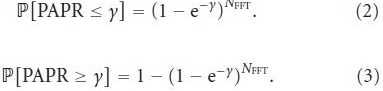
As an example of using this simple approximation, which
becomes increasingly tight increasing the FFT size, it is easy
to check that a PAPR of 9 dB is exceeded with a probability of
0.5 assuming NFFT = 2048, while a PAPR of 12 dB is exceeded
with a probability of 2.7 · 10-4.
This argument motivates the use of a PAPR reduction
technique, in order to lower the PAPR and drive the satellite
amplifier with a lower back-off. Power efficiency is at a prime
in satellite communications, and an eventual reduction of
the back-off implies an improvement in the link budget
and an eventual increase of the coverage area. Amongst all
requisites for PAPR reduction techniques (see [9, 10] for a
general overview), the compatibility with the LTE standard is
still fundamental. Secondly, the receiver complexitymust not
be significantly increased. Furthermore, no degradation in
BER will be tolerated, because it would require an increased
powermargin. Finally, the PAPR reductionmethod will cope
with the severe distortion given by the satellite: even if the
amplifier has an ideal pre-distortion apparatus on-board, it
is operated near to its saturation, where a predistorter could
not invert the flat HPA characteristic. The cascade of an ideal
predistorter and the HPA is the so-called ideal clipping or
soft limiter. In such a scenario, if the PAPR is lower than
the IBO the signal will not be distorted, while if the PAPR is
significantly higher the signal will be impaired by non-linear
distortion. Thus, the PAPR reduction technique should offer
a good PAPR decrease for almost all OFDM symbols, rather
than a decrease which can be experienced with a very low
probability.
Several techniques have been proposed in the literature,
and even focusing on techniques which do not decrease
the spectral efficiency, the adaptation to satellite scenario
remains an issue: this is the case of Tone Reservation [11–
13], the intermodulation products of satellite amplifier prevent using this technique, while it is very popular in
the wired scenario and when the amplifier is closer to its
linear region. The Selected Mapping technique [14, 15],
although easy and elegant, needs a side information at the
receiver. The side information can be avoided, at expense
of a significant computational complexity increase at the
receiver. Companding techniques (see [10] and references
therein) offer a dramatic reduction in PAPR and do not
require complex processing. On the other hand, there is a
noise enhancement, which turns out to be an important
source of degradation at the very low SNRs used in satellite
communications.
The Active Constellation Extension (ACE) technique [16]
fulfills those requirements, moreover the power increase
due to PAPR reduction is exploited efficiently, obtaining an
additional margin against noise. The ACE approach is based
on the possibility to dynamically extend the position of some
constellation points in order to reduce the peaks of the time
domain signal (due to a constructive sum of a subset of
the frequency domain data) without increasing Error Rate:
the points are distanced from the borders of their Voronoi
regions. The extension is performed iteratively, according to
the following procedure.
(1) Start with the frequency domain representation of a
OFDM symbol.
(2) Convert into the time-domain signal, and clip all
samples exceeding a given magnitude Vclip. If no
sample is clipped, then exit.
(3) Reconvert into the frequency domain representation
and restore all constellation points which have been
moved towards the borders of their Voronoi regions.
(4) Go back to 2 until a fixed number of iteration is
reached.
This algorithm is applied to data carriers only, excluding
thus pilots, preamble/signalling and guard bands. In the
performance evaluation of the algorithm, the amplitude
clipping value is expressed in term of the corresponding
PAPR, which is called PAPR-Target in the following.
The most critical point of thismethod is the choice of the
clipping level Vclip: a large value for Vclip (which corresponds
to an high PAPR-Target) will yield a negligible power increase
and a poor convergence, since signal is unlikely to be clipped.
On the opposite extreme, a very low clipping level will yield
again a poor convergence and a negligible power increase.
In fact, considering the above algorithm, almost all points
will be moved by clipping in step-2 and then restored by the
constellation constraint enforcing in step-3. A compromise
value, which will lead to a PAPR around 5 or 6 dB is advisable,
yielding a good convergence and a slight energy increase,
due to the effectiveness of the extension procedure. Although
there are other ACE strategies [16], the solution presented
here is attractive because it can be easily implemented both
in hardware and software, as reported in [17].
3.3. Random Access Signal Detection. The Random Access
Channel (RACH) is a contention-based channel for initial
uplink transmission, that is, from mobile user to base station.
While the Physical RACH (PRACH) procedures as defined
in the 3G systems are mainly used to register the terminal
after power-on to the network, in 4G networks, PRACH is in
charge of dealing with new purposes and constraints. In an
OFDM based system, in fact, orthogonal messages have to be
sent, thus the major challenge in such a system is to maintain
uplink orthogonality among users. Hence both frequency
and time synchronization of the transmitted signals from
the users are needed. A downlink broadcast signal can be
sent to the users in order to allow a preliminary timing and
frequency estimation by the mobile users, and, accordingly
a timing and frequency adjustment in the return link. The
remaining frequency misalignment is due to Doppler effects
and cannot be estimated nor compensated. On the other
hand, the fine timing estimation has to be performed by
the base station when the signals coming from users are
detected. Thus, the main goal of PRACH is to obtain fine
time synchronization by informing the mobile users how
to compensate for the round trip delay. After a successful
random access procedure, in fact, the base station and the
mobile user should be synchronized within a fraction of the
uplink cyclic prefix. In this way, the subsequent uplink signals
could be correctly decoded and would not interfere with
other users connected to the network.
PRACH procedure in 4G systems consists in the transmission
of a set of preambles, one for mobile user, in
order to allocate different resources to different users. In
order to reduce collision probability, in the LTE standard,
Zadoff-Chu (ZC) sequences [18], known also as a Constant
Amplitude Zero Autocorrelation (CAZAC) sequences, are
used as signatures between different use, because of the good
correlation properties. The ZC sequence obtained from the
u-th root is defined by (4) where NZC is the preamble length in samples and it has been
set to 839. ZC sequences present very good autocorrelation
and cross-correlation properties that make them perfect
candidates for the PRACH procedure. In fact, orthogonal
preambles can be obtained cyclic rotating two sequences
obtained with the same root, according to the scheme shown
in Figure 3 and the expression (5) where NCS is the number of cyclic shifts. It can be easily
verified that the cross correlation function presents NCS
peaks and NCS zero correlation zones. Figure 4(a) shows a
magnification of the cross correlation function for different
shifts considering NCS = 64. It will be noted that there are
NCS-2 zero correlation zones with length equal to 12 samples
and the last zero correlation zone with 20 samples. Preambles
obtained from different roots are no longer orthogonal but,
nevertheless, they present good correlation properties.
Considering a 4G system via satellite, the number of
users to be allocated in each cell depends on the system design.
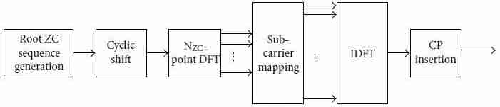
Figure 3: ZC generation in time domain processing.
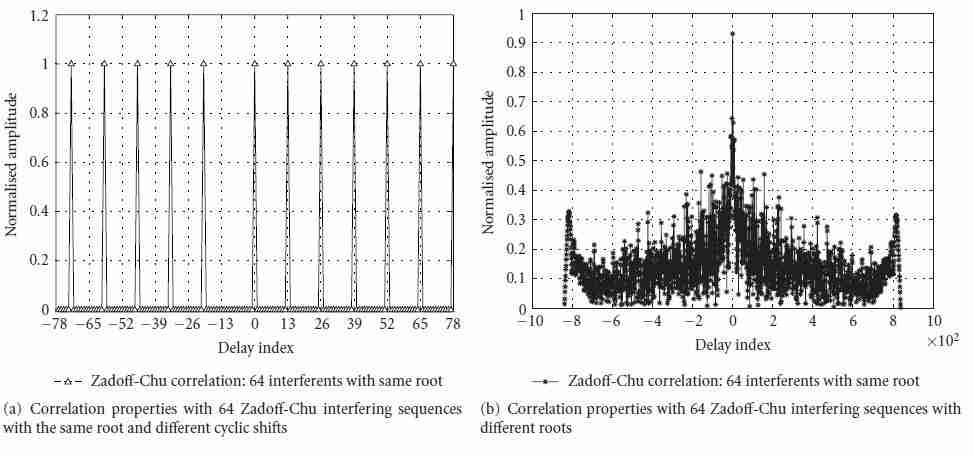
Figure 4: Detection properties in the presence of interferers.
Table 1: ZC allocation for GEO satellite scenario.
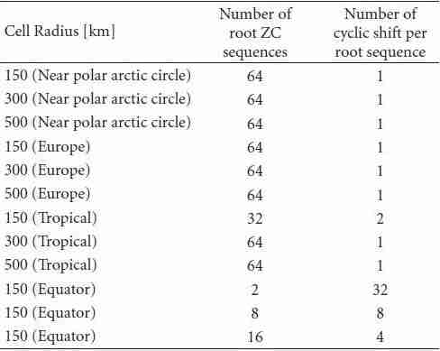
The zero correlation zone of the preambles has to
be larger then the maximum round trip propagation delay,
depending on cell radius andmultipath delay. The number of
root ZC sequences and the number of cyclic shift sequences
depend on cell radius and on the geographical position, and
they are reported in Table 1 for GEO satellites. Note that the worst case corresponds to the presence of 64 sequences
obtained from different roots. In this case, the satellite has
to detect each sequence even between the interference from
the others. Figure 4(b) shows the correlation function in
a scenario like this, and it is worthwhile noting that the
peak can once more be detected, also in the presence of
63 interferers. Detection performance in terms of Receiver
Operating Characteristics (ROC), that is, Missed Detection
Probability (Pmd) as a function of False Alarm Probability
(Pfa) have been reported for different numbers of interferers
in Figure 5. It will be highlighted that the detection has been
performed in the frequency domain and a Non-Coherent
Post-Detection Integration (NCPDI) [19] scheme has been
adopted. Finally, the results are shown in a AWGN scenario
with a signal to noise ratio, Es/N0, equal to 0dB.
4. Upper Layer FEC Analysis
In this section, we propose a UL-FEC technique working on
top of the PHY layer. It is well known that channel coding
can be performed at different layers of the protocol stack.
Two are the main differences which arise when physical layer
or upper layer coding is addressed: the symbols composing
each codeword, and the channel affecting the transmitted
codeword. Indeed, at physical layer the symbols involved in
the coding process typically belong to the Galois Field of order m, GF(m). Nevertheless, also non binary codes can be
adopted.Working at upper layer each symbol composing the
UL codeword can be made up of packets of bits, depending
on the application level.
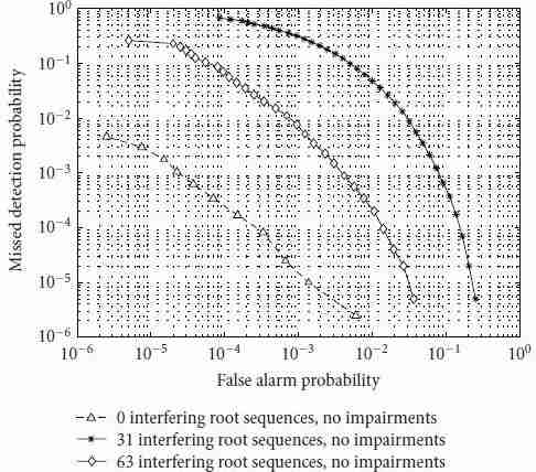
Figure 5: ROC in AWGN channel with Es/N0 = 0.0 dB without
interference, and with interferers with different roots.
In order to build the UL-FEC technique on solid ground,
the design and analysis has been carried out starting from
the Multi Protocol Encapsulation Forward Error Correction
Technique (MPE-FEC) adopted by the DVB-H standard
[20], and successively enhanced and modified in the framework
of the DVB-SH [1] standardization group.With respect
to the MPE-FEC approach, the implementation of the ULFEC
technique for this framework has required to adapt the
parameter setting to the LTE physical layer configurations. In
the following, we adopt this terminology:
i) k: the UL block length, that is the number of
systematic symbols to be encoded by the UL encoder
(ii) n: the UL codeword length, that is the number of UL
symbols produced by the UL encoder
(iii) k′: the actual UL-FEC block length if zero-padding is
applied
(iv) n′: the actual UL-FEC codeword length if zeropadding
and/or puncturing is applied
(v) NJCC: number of jointly coded channels at physical
layer
(vi) SJCC: size of each channel in bytes
(vii) SUL-CRC: size of the upper layer Cyclic Redundancy
Check (CRC) in bytes
(viii) SPHY-CRC: size of the physical layer CRC in bytes
(ix) KPHY: physical layer block length in bytes.
As in MPE-FEC, we define the UL-FEC matrix as a matrix
composed of a variable number of rows (n_of_rows) and n
columns. Each entry of the matrix is an UL-symbol, that
is, 1 byte. The first k columns represent the systematic part
of the matrix and are filled with the systematic UL-symbols
coming from the higher level. The last n - k columns carry
the redundancy data computed on the first k columns. It is
worthwhile to notice that the n and k values depend on the
selected UL code rate only, while n_of_rows is a parameter
chosen accordingly to the physical layer configuration and
is set by using the following formula: n_of_rows = KPHY -
SPHY-CRC - NJCCSUL-CRC. As a consequence, the number of
bytes available for each channel in a given UL-FEC matrix
column is SJCC = n_of_rows/NJCC. With this configuration,
the following operations must be sequentially performed.
(1) The information data coming from higher layer are
written columns-wise in the systematic data part of
the UL-FEC matrix.
(2) A Reed-Solomon (RS) encoding (n, k) is performed
on each row producing the redundancy part of the
UL-FEC matrix.
(3) The data are transmitted column-wise.
(4) An UL-CRC is appended after each group of SJCC
bytes.
(5) Each group of KPHY = NJCC(SJCC + SUL-CRC) bytes
composes a physical layer information packet.
(6) The PHY-CRC is appended to each physical layer
information packet according to the LTE specifications[7].
For sake of simplicity, we adopt the same RS mother code
provided in [20], which is an RS(255,191). The code rate of
this mother code is 3/4. Further code rates can be achieved
by using padding or puncturing techniques. For instance,
if a UL-FEC rate 1/2 is needed, zero-padding is performed
over the last 127 columns of the systematic data part of the
UL-FEC matrix, yielding to k′ = 64 and n′ = 128. The
choice of this RS code allows fully compatibility with DVB-H
networks.
It is important to note how the application of the CRC
at UL and physical layer has an impact on the overall system
performance. To better evaluate this impact, we distinguish
to study cases:
(i) .Case-A: only the PHY-CRC is considered (SUL-CRC =
0). In this scenario, the receiver is not able to check
the integrity of a single UL packet carried within
the same physical layer information packets. This
basicallymeans that if error is detected in the physical
layer information packet, all UL packets will be
discarded;
(ii) Case-B: both PHY and UL CRC are applied.
It is quite obvious that Case-B outperforms Case-A. In fact,
if only a small fraction of bits are wrong after physical layer
decoding, Case-B is able to discard only the UL packets in
which erroneous bits are present, while Case-A discards all
NJCC carried within the physical layer information packets.
The price to pay is an increased overhead of Case-B with
respect to Case-A due to the extra CRC bits appended.
At the receiver side, depending whether Case-A or Case-
B is taken into account, CRC integrity must be performed
at different levels. If the Case-A is considered, only the CRC
at physical layer determines the data reliability; whereas in
the Case-B, the PHY-CRC could be ignored and the data
reliability is only determined by the UL-CRC. Then, the ULFEC
matrix is filled with the reliable data. In particular, for
the Case-A an entire column is marked as reliable or not
reliable, while in the Case-B the UL-FEC matrix columns
could be partially reliable. Finally, the RS(n, k) decoding is
performed on each row. If the number of reliable position
in a row is at least k, the decoder is able to successfully
decode the received information, and all unreliable positions
are recovered.
The UL-FEC protection capability against burst of errors
can be characterized by the so-called Maximum Tolerable
Burst Length (MTBL) [21], which consists in the maximum
time protection that the UL-FEC technique can provide. The
MTBL depends on both UL-FEC parameters and PHY data
rate. In our proposal one PHY information packet is mapped
in one column of the UL-FEC matrix. Since we are dealing
with MDS codes, the decoder is able to successfully decode
if at least k′ columns are correctly received in the UL-FEC
matrix. Thus, the MTBL is simply given by the time taken
by transmitting n′ - k′ columns, that is, the duration of
n′ - k′ information packets. The MTBL can be increased
by adopting a sliding encoding mechanism [22]. The sliding
encoding is a UL interleaver mechanism: a UL-FEC encoder
implementing sliding encoding selects the k′ data columns
from a window (SW) among the UL-FEC matrices and
spreads the n′ - k′ parity sections over the same window.
Basically, the same effect could be obtained by first normally
encoding SW frames and then interleaving sections among
the encoded SW frames. The total protection time TPTUL
achievable at upper layer by means of such a technique is
given by TPTUL = n′ · SW · TTTI.
5. Simulation Results
Here, we discuss separately the numerical results obtained
by implementing the solutions presented in Section 3. The
following general assumptions have been considered during
the implementation of all techniques.
The LTE transmitted signal occupies 5MHz of bandwidth,
Na = 300, located in S-band (central frequency
f0 = 2GHz), the sub-carrier spacing is Δf = 15 kHz, and
FFT/IFFT size is fixed to NFFT = 2048. The long cyclic prefix
is assumed, Ncp = 512, thus Nsymb = 12 OFDM symbols
are transmitted in each TTI. The resulting OFDM symbols
duration is TOFDM = 83.33 μs, including the cyclic prefix
duration of Tcp = 16.67 μs.
5.1. Inter-TTI Improvements. For evaluating the inter-TTI
proposal, the turbo encoder is fed with 2496 information
bits, while the circular buffer size is assumed to be 6300, thus
resulting in an actual system code rate equal to R≅2/5. All
simulations have considered QPSK modulation.
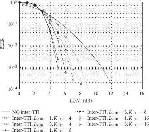
Figure 6: BLER versus Eb/N0. Terminal speed is equal to 30 km/h.
Figure 6 shows the block error rate (BLER) performance
versus Eb/N0, with Eb being the energy per information
bit and N0 the one-sided noise power spectral density. The
curves refer to a user terminal speed of 30 km/h. The solid
line curves represent the cases in which the number of
transmitted OFDM symbols for each retransmission (LSUB)
is 1, resulting in a total number of retransmissions RTTI = 12,
while the dashed line curves depict the case with LSUB = 3
and RTTI = 4. In these configurations, we set the value of
KTTI such that the total protection time TTTI is larger than
the channel coherence time Tc, which for these simulations
is about Tc≅9ms. (This is the coherence time of the small
scale fluctuations, and it depends directly from the terminal
speed and the central carrier frequency.) In particular, the
simulated values KTTI are 4, 8, 16. As it can be observed,
the solid line curves always outperform the dashed line ones.
This is easily explained considering the different diversity
granularity: in the case of LSUB = 1, each OFDM symbol
is transmitted in a separated TTI. Therefore, the codeword
spanned over the 12 OFDM symbols composing the entire
TTI can benefit of diversity degree equal to 12. On the other
hand, if the case of LSUB = 3 is considered, the degree
diversity is reduced to 4. It is worthwhile to note the large
performance enhancement yielded by the adoption of the
inter-TTI technique. For instance, looking at Figure 6, the
performance gain at BLER = 10-3 increases up to 6 dB in
the case of LSUB = 1, and up to 4 dB considering LSUB = 3.
5.2. ACE Performance. The results of the ACE algorithm for
PAPR reduction are discussed. First of all, the CCDF of PAPR
distribution have been analyzed for verifying the effectiveness
of the selected method.
Figures 7 and 8 show PAPR distribution for QPSK
and 16QAM, respectively. As it can be seen, if the PAPRTarget
is too low, the CCDF curve has a poor slope.
Increasing the PAPR-Target, the curve is shifted left until a certain value, then the steepness increases and, if the PAPRTarget
is furthermore increased, the curve is shifted right,
maintaining the same steepness. This phenomenon is more
evident for QPSK modulation rather than for 16QAM, and
this difference can be explained considering that all QPSK
constellation points can be moved in some directions by the
ACE algorithm, while for 16QAM the inner points must be
immediately restored, and the points on the edges have only
one degree of freedom.
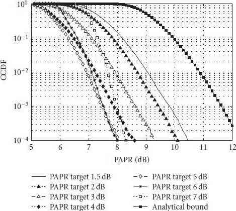
Figure 7: PAPR CCDF with QPSK modulation.
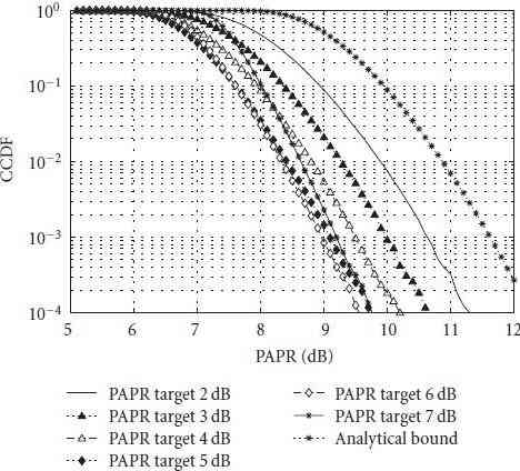
Figure 8: PAPR CCDF with 16QAM modulation.
A more interesting figure of merit related to this PAPR
reduction technique is the improvement in terms of bit
error rate, which summarizes the impact of PAPR reduction
on the end-to-end performance. Figure 9 shows the BER
improvement in a frequency selective channel, with the amplifier Input Back-Off (IBO) set to 3 dB. The 16QAM
modulation is considered, the coding rate is r = 3/5, and the
packet size is chosen equal to 7552 bits. As shown in Figure 9,
there is a gain of almost 0.5 dB if the PAPR-Target is kept low;
the gain is slightly lower if the PAPR Target is chosen in order
to maximize the beneficial effects of ACE technique in terms
of PAPR CCDF. This result can be justified by considering
the worst-case conditions assumed in these simulations: the
amplifier driven 3 dB far from saturation requires a PAPR
value as low as possible, while the slight energy increase
is conveniently exploited in such a severe fading channel
environment.
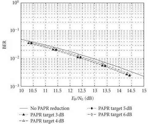
Figure 9: BER performance using PAPR techniques with 16QAM
and code-rate = 3/5.
5.3. Redundancy Split Analysis. A comparison between the
UL-FEC and the inter-TTI interleaver technique is reported.
In order to make a fair comparison between these two techniques,
in the following we keep constant the overall spectral
efficiency by distributing the redundancy between UL-FEC
and physical layer. Figure 10 shows the numerical results
obtained in the case of assuming the terminal speed equal
to 3 km/h, and ideal channel estimation. The performance is
measured in terms of BLER versus Eb/N0. All reported curves
have a spectral efficiency equal to 4/5 bit/s/Hz. In the inter
TTI case, we have considered the coding rate r = 2/5 and
QPSK modulation, and we have varied both the interleaver
depth and the subframe size. On the other hand, the ULFEC
solution have been implemented by considering r =
4/5 with QPSK modulation at the physical layer, and the
(k′ = 64, n′ = 128) code at the upper layer. Since the
considered UL-FEC protection spans over n′ = 128, that
corresponds to 128 ms, the most comparable protection time
provided by the inter-TTI approach is obtained by adopting
the parameters KTTI = 40 and LSUB = 3, which still guarantee
orthogonal retrasmissions. In this case, the physical layer
codeword spans over KTTI · 4 = 160 TTIs, that is, 160 ms.
From the analysis of the results, we can state that on the one hand, the inter TTI techniques outperforms the UL-FEC
technique, which can be justified recalling that at physical
layer the decoder can exploit soft information, thus achieving
much better performance with respect to the hard decoding
performed at upper layer. On the other hand, the inter-TTI
technique requires a large memory buffer at the output of
the base-band processor. A through complexity analysismust
be carried out to this respect in order to understand the
hardware feasibility of the assumption considered for the
inter-TTI interleaving case.
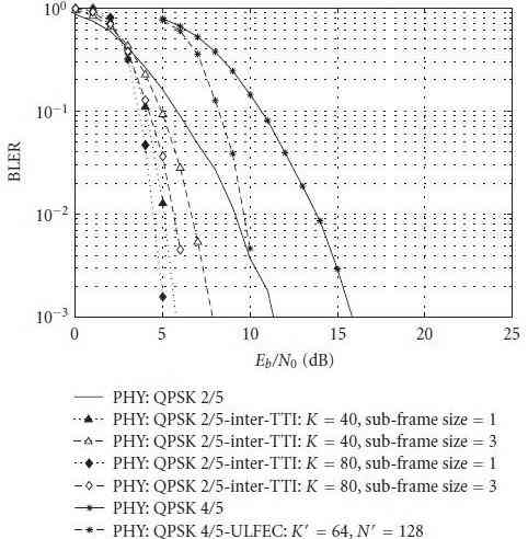
Figure 10: Comparison between Inter-TTI and UL-FEC techniques.
5.4. End-to-End Performance Evaluation. In this section,
the results obtained considering end-to-end simulations in
realistic satellite propagation scenario are analyzed. To this
aim, we have adopted the Land Mobile Satellite (LMS)
channel model proposed in [23], which is based on measurement
campaigns. This channel model is characterized by
a three states Markov model. Each state describes different
propagation conditions, that are line of sight, moderate
shadowing conditions, and deep shadowing conditions.
By suitably setting the Markov chain parameters, several
environment can be modeled. In our analysis we have
considered an elevation angle of 40 degrees and the following
environments: open area [O], Suburban [S], Intermediate
tree shadow [ITS], Heavy Tree Shadow [HTS]. Such environments
are characterized by long fading events due to
the superposition of shadowing effects. It is quite obvious
that applying the proposed UL-FEC technique without any
interleaver working at UL does not allow to cope with
such channel impairments. Indeed, the MTBL achievable by
adopting UL-FEC without sliding interleaving (SW = 1) is
in the order of hundreds milliseconds. To increase the MTBL
we adopt the sliding window encoding technique. As already
mentioned, this technique basically consists in applying a
block interleaver at UL.
In order to correctly evaluate the achievable performance
of the proposed UL-FEC technique, we have fed the ULFEC
decoder with time series. Since the fading is frequency
flat and for low to medium terminal speeds time selectivity
is negligible with respect to the TTI duration (channel
coherence time equal to 9ms at 30 km/h, whereas TTI
duration equal to 1 ms for LTE), we can assume that the
SNR is constant within the whole TTI (both in frequency
and in time). (Again, this fading coherence time is referred
to the small scale fluctuations, while the large scale is
taken into account in the LMS channel parameters.) Under
these assumptions, the BLER time series can be generated
using a simplified method, that does not require the actual
simulation of the whole physical layer chain. The adopted
procedure is depicted in Figure 11, and is made up by the
following steps:
(1) perform AWGN simulations (including NL distortion),
to obtain the function BLER versus Eb/N0;
(2) generate the Perez Fontan channel coefficients,
obtaining signal levels relative to LOS component;
(3) calculate the received C/N0 value in LOS conditions;
(4) map the instantaneous C/N0 value into Eb/N0;
(5) generate the time series, producing a “1” (wrong
block) or a “0” (correct block) according to the
following algorithm: if [uniform-random-variable <
BLER (Eb/N0∗)] then time-series-value = 1, else timeseries-
value = 0.
In order to get a synthetic analysis of the results, we have
assessed the Erroneous Seconds Ratio (ESR) criterion. The
ESR was also considered by the DVB-SSP [24] group to be
the most relevant performance parameter for the assessment
of the impact on the video quality. In particular, we take
into account the ESR5(20) criterion: ESR5(20) is fulfilled
for a given time interval of 20 seconds if the percentage
of erroneous seconds in the same time interval does not
exceed 5%, which corresponds to amaximum of 1 erroneous
second. The percentage of time satisfying the ESR5(20)
criterion represents the “ESR5(20) fulfillment percentage.”
The conclusions of this analysis are summarized in Figure 12,
where the achievable spectral efficiency is reported as a
function of the C/N required to satisfy the ESR5(20) criterion
at 90%. The spectral efficiency is computed considering
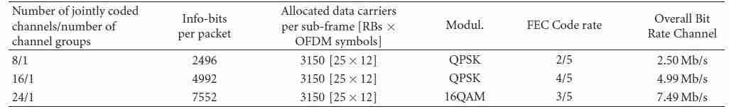
the PHY configurations listed in Table 2. Notably, since
usually in a LTE frame both information and control
data are transmitted, we assumed that the equivalent of
1 OFDM symbol per TTI, that is, 1/12 of the TTI, is
completely dedicated to the transmission of control data. As
a consequence, the PHY spectral efficiency resulting from
Table 2 has been reduced by a factor (11/12).
In Figure 12, each curve represents the performance of
In Figure 12, each curve represents the performance of
the QPSK constellation in a given scenario and for a given
UL-FEC coding rate. The connected markers in each curve
represent the corresponding PHY configurations in a given scenario and for a given UL-FEC coding rate. Regarding
the UL parameters, two configuration have been taken into
account: rate 1/2 (n′ = 128, k′ = 128) and rate 3/4 (n′ =
191, k′ = 255). The adopted sliding window size has been
set to SW = 101 for the rate 1/2 case, and 50 for the
rate 3/4, yielding to a total protection time at UL equal
to TPTUL = 12.928 s, and TPTUL = 12.75 s, respectively.
Notably, for the 16QAM constellation, only one PHY FEC
scheme has been considered. Interestingly, the lower ULFEC
protection, that is, 3/4, always outperforms, at the same
total spectral efficiency, the higher UL-FEC protection, with
the only exception of the Heavy Tree Shadow scenario. In
that case, the extremely challenging propagation conditions
calls in fact for a very strong protection along with a quite
demanding link budget.
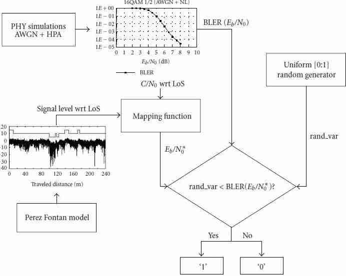
Figure 11: Block diagram of the procedure adopted for generating the time series.
Table 2: Adopted LTE Physical layer configurations.
6. Conclusions and Recommendations
The adoption of the 3GPP LTE air interface to broadband
satellite networks has been evaluated. The rationale for this
choice was the maximization of the commonalities with the
terrestrial air interfaces, so as to reduce both non-recurrent
engineering and production costs, while easing interworking
procedures. The selected numerologies for forward and
reverse links are standard compatible. In this sense, the
results produced are significant from the 3GPP point of
view.
Regarding time domain fade mitigation techniques, one
of the major findings consists in a way to obtain the above
diversity in an almost standard compatible way. This is
the inter-TTI technique, which has been shown to bring
significant benefits without touching the physical layer
definition.
PAPR reduction algorithms, coupled to predistortion
techniques, are a novelty for OFDM transmission through a
satellite. We have explored this architecture and our results
show that the PAPR itself can be reduced by 2 to 4 dB
(guaranteed at 99.9%), which translates into the possibility
to reduce the OBO by about 0.7 dB and to gain about 0.5 dB
in Eb/N0 for typical quality of services. All in all, we can expect a gain in total degradation around 1 dB, which is
certainly not negligible.
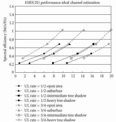
Figure 12: Overall (PHY+UL) spectral efficiency versus C/N for
90% ESR5(20).
Regarding frame acquisition procedures, they are quite
specific for LTE air interface. The design of acquisition
sequences for 3GPP LTE has been performed adapting it
to the different requirements set by satellite transmission
involving the use of large geographic beams.
Additionally, in order to further extend the link reliability
over the satellite link, the use of UL-FEC techniques has been
investigated. Simulation results clearly show that the ULFEC
technique is a very effective solution that can drastically
improve the achievable block error rate and ESR5(20)
performance.
In order to provide useful guidelines for the system
design, the analysis of the optimum redundancy split
between physical and upper layer coding has been performed.
In this case, results show that in most cases it is
beneficial to limit the protection at physical layer in order
to ease channel estimation and to compensate the reduced
performance through a stronger UL coding. The rationale
behind this conclusion is that the UL-FEC benefits a larger
time diversity thus performing significantly better than the
physical layer coding in almost all scenarios.
Acknowledgment
This work is supported in part by the ESA contract no.
20194/06/NL/US, “Study of Satellite Role in 4G Mobile
Networks.”
References
[1] ETSI EN 302 583, “Digital video broadcasting (DVB); framing
structure, channel coding andmodulation for satellite services
to handheld devices (SH) below 3 GHz,” v1.1.1, March 2008.
[2] The Integral Satcom Initiative (ISI), “ISI strategic research
agenda,” FP7 Technology PlaTform, v1.1, January 2006,
http://www.isi-initiative.eu.org/isi joomla.
[3] ETSI TR 102 443, “Satellite earth stations and systems (SES);
satellite component of UMTS/IMT-2000; evaluation of the
OFDM as a satellite radio interface,” v1.1.1, August 2008.
[4] 3GPP TS36.211, “3rd Generation Partnership Project; Technical
Specification Group Radio Access Network; Evolved Universal
Terrestrial Radio Access (E-UTRA); Physical Channels
and Modulation (Release 8),” v8.2.0, March 2008.
[5] “IEEE standard for local and metropolitan area networks,
part 16: air Interface for fixed and mobile broadband wireless
access systems amendment 2: physical and medium access
control layers for combined fixed and mobile operation in
licensed bands and corrigendum 1,” IEEE Computer Society
and the IEEE Microwave Theory and Techniques Society, 20
February 2006.
[6] G. E. Corazza, P. Britten, I. Buret, et al., “Defining the
role of satellite communications in 4G,” in Proceedings of
the 8th World Wireless Congress on Fourth Generation Mobile
Communications (WWC ’07), pp. 60–64, San Francisco, Calif,
USA, May 2007.
[7] 3GPP TS36.212, “3rd Generation partnership project; technical
specification group radio access network; evolved universal
terrestrial radio access (E-UTRA); multiplexing and channel
coding (release 8),” v8.2.0, March 2008.
[8] M. Papaleo, M. Neri, G. E. Corazza, and A. Vanelli-Coralli,
“Using LTE in 4G satellite communications: increasing time
diversity through forced retransmission,” in Proceedings of the
10th International Workshop on Signal Processing for Space
Communications (SPSC ’08), Rhodes Island, Greece, October
2008.
[9] S. H. Han and J. H. Lee, “An overview of peak-to-average
power ratio reduction techniques for multicarrier transmission,”
IEEEWireless Communications, vol. 12, no. 2, pp. 56–65,
2005.
[10] T. Jiang and Y.Wu, “An overview: peak-to-average power ratio
reduction techniques for OFDM signals,” IEEE Transactions on
Broadcasting, vol. 54, no. 2, pp. 257–268, 2008.
[11] J. Tellado, Peak to average power reduction for multicarrier
modulation, Ph.D. dissertation, Stanford University, Stanford,
Calif, USA, 2000.
[12] B. S. Krongold and D. L. Jones, “An active-set approach for
OFDM PAR reduction via tone reservation,” IEEE Transactions
on Signal Processing, vol. 52, no. 2, pp. 495–509, 2004.
[13] S. Janaaththanan, C. Kasparis, and B. G. Evans, “A gradient
based algorithm for PAPR reduction of OFDM using tone
reservation technique,” in Proceedings of the 67th IEEE Vehicular
Technology Conference (VTC ’08), pp. 2977–2980, Marina
Bay, Singapore, May 2008.
[14] R. W. Bäauml, R. F. H. Fischer, and J. B. Huber, “Reducing
the peak-to-average power ratio of multicarrier modulation
by selected mapping,” Electronics Letters, vol. 32, no. 22, pp.
2056–2057, 1996.
[15] M. Breiling, S. H. Mller-Weinfurtner, and J. B. Huber, “SML
peak-power reduction without explicit side information,”
IEEE Communications Letters, vol. 5, no. 6, pp. 239–241, 2001.
EURASIP Journal onWireless Communications and Networking 13
[16] B. S. Krongold and D. L. Jones, “PAR reduction in OFDM
via active constellation extension,” IEEE Transactions on
Broadcasting, vol. 49, no. 3, pp. 258–268, 2003.
[17] ETSI EN 302 755, “Digital video broadcasting (DVB); frame
structure channel coding and modulation for a second
generation digital terrestrial television broadcasting system
(DVB-T2),” April 2008.
[18] D. C. Chu, “Polyphase codes with good periodic correlation
properties,” IEEE Transactions on Information Theory, vol. 18,
no. 4, pp. 531–532, 1972.
[19] A. J. Viterbi, CDMA Principles of Spread Spectrum Communications,
Addison-Wesley Wireless Communications Series,
Addison-Wesley, Reading, Mass, USA, 2nd edition, 1995.
[20] ETSI TR 102 377, “Digital video broadcasting (DVB); DVB-H
implementation guidelines,” v1.2.1, November 2005.
[21] M. Papaleo, R. Firrincieli, S. Cioni, et al., “Link layer FEC in
DVB-RCS: performance evaluation in nLoS conditions,” in
Proceedings of the 67th IEEE Vehicular Technology Conference
(VTC ’08), pp. 2972–2976, Marina Bay, Singapore, May 2008.
[22] M. Papaleo, R. Firrincieli, G. E. Corazza, and A. Vanelli-
Coralli, “On the application of MPE-FEC to mobile DVBS2:
performance evaluation in deep fading conditions,” in
Proceedings of the InternationalWorkshop on Satellite and Space
Communication (IWSSC ’07), pp. 223–227, Salzburg, Austria,
September 2007.
[23] F. Péerez-Fontáan,M. Váazquez-Castro, C. E. Cabado, J. P. García,
and E. Kubista, “Statistical modeling of the LMS channel,”
IEEE Transactions on Vehicular Technology, vol. 50, no. 6, pp.
1549–1567, 2001.
[24] ETSI TM-SSP252-Revision 6 (2007-05), “Digital video broadcasting
(DVB); DVB-SH implementation guidelines”.
Íŕçŕä â áčáëčîňĺęó