
Abstract
Content
- Introduction
- 1. Theme urgency
- 2. Goal and tasks of the research
- 3. Review of Research and Development
- 4. Geometrical optics model of the system of protection from glare
- 5. The algorithm for finding the coordinates of a bright light source
- Conclusion
- List of sources
Introduction
The eyes of man, by nature, highly vulnerable, especially when it comes to work in hostile environments, such as when electric welding [5] or the blinding lights of oncoming cars. During the welding and metal cutting occurs bright light radiation, hazardous to the eyes. Infrared and ultraviolet rays can cause burns of the retina, and the bright flashes of light can damage the cornea. However, these dangers can be avoided if we have the necessary means of protection and proper use of them.
Glare occurs because of certain peculiarities of the person. The fact that the eye - an extremely sensitive organ, so you can perfectly see the steppes and in the night and the sun on a fine winter day. The human eye can perceive the brightness of which differ from each other a billion times.
Despite the universality of human vision, it has a major drawback: the sudden change in the brightness eyes need a lot of time trying to adapt a new light. Adaptation of the pupil to the new coverage takes a few tens of seconds. In a sudden sharp change in lighting a man can not see almost nothing
1. Relevance of the topic
Protection of operators working with bright flashes of light is a very urgent task. For example, welding technology has reached unprecedented heights, which ten years ago seemed impossible, but the preservation of the health of the welder is not fully resolved [4]. An electric arc, used in welding, can damage eyesight or blind, and leads to fatigue and decreased performance. This problem is concerned, many European firms in the study of personal protective equipment invested huge amounts of money. At this point actual creation of intellectual protection that can react to bright flashes of light.
Eyes during welding must be protected from harmful radiation, as they are defeated in a split second and instantly felt - from the blinding light to burn the cornea. Masks with the usual dark glasses uncomfortable to hold, they do not provide the necessary protection for the welder. Permanent visual inspection of the welding process without the need for raising and lowering the mask improves quality and increases productivity of welding
2. The purpose and objectives of the study
The aim of the study is to develop an automated system security management view of the dazzling bright flashes of light when the welding work.
In the development of an automated control system is protected from glare are the following functions:
- Determining the origin bright source of light in an optical system cameras.
- Calculation of coordinates in space.
- Management protective agent.
Block diagram of the system can be represented as follows (Fig. 1):
Figure 1 - Block diagram of the automated control system is protected from glare
(Animation: 7 shots, 5 cycles of repetition, 31 KB)
3. Review of Research and Development
At the present time, there were "smart" mask of a new generation of auto darkening filter [7]. One of them - a mask, produced by SPERIAN. SPERIAN produced a batch of brand masks "STORM". The mask is designed for all types of welding with adjustable delay return to the light position, in any light, in the current range of 1 to 500 A in manual welding (MMA), MIG (MIG / MAG), argon-arc welding (TIG), plasma cutting / welding, gas cutting / welding.
The mask has two modes of dimming control - automatic and manual.
The filter consists of seven different levels of protection - UV / IR filter. UV / IR filter continually blocks harmful radiation, whether it is enabled or disabled. High speed operation (of 0.18 ms at room temperature and 0.12 ms at 55 ° C) and the original filter control algorithm provides a minimum load on welder's eyes throughout the day.
A guard automatically adjusts the degree of darkening, depending on the intensity of the glow of the arc: a unique technology allows you to filter svetosensorov automatically select the desired level of darkness and continually adapt it to changing conditions, capturing and evaluating the intensity of the electric arc.
Features of the device:
- Two modes adjust the blackout: a fully automatic or manual adjustment of the range 4/9-13 DIN
- When the panel automatically dimming the possibility of further adjustments in the range of ± 1 DIN
- control panel is located on the left side of the left outer panel that allows the welder to adjust the degree of darkness, without removing the panel
- Larger field of view and accurate color provides excellent visibility welder to weld the object. Indications on the digital indicator panels welders welder perfectly visible, there is no need to remove the shield
- Availability mode to prevent the grinding operation panel on the flying sparks from mechanical processing
- Adjustable sensitivity and speed of lightening
- Power - solar cell and batteries, there is no need to turn on / off plate (automatic activation)
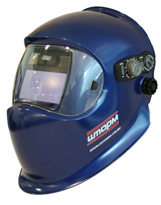
Figure 2 - Welding Mask "Storm"
Product Specifications:
- Adjustable sensor bar eliminates the effects of ambient light sensors, changing the angle of perception between 60 ° and 120 °
- mode - manual or automatic
- Adjusting the dimmer in the range 9-13 DIN
- grinding mode to prevent the operation panel on the flying sparks
- button to adjust the sensitivity of the perception sensors arc
- lightening speed regulation for the protection of the afterglow of the weld, and to set individual settings
- Batteries 3V, 2 pcs.
4. Geometrical optics model of the system of protection from glare
The work of any television measurement system is based on the fact that the projected optical system the optical field is converted to a television transmitter, by reading the information in the frame two-dimensional array of discrete video samples [1 -2]. This video contains NhM elements and is a rectangular matrix having M rows and N columns, where M and N - some unequal positive integers. We can assume that during the scan television frame offset of the object image by detecting the sensor slightly and it can be assumed to be zero, and therefore the effects of image blur can also be neglected.
The image forming optical system of the object in the plane of the camera matrix photodetector. The analog video signal output from the video matrix is converted into a digital signal using ADC and received for processing in the microprocessor.
A video optical system (Fig. 3) forms on the surface of a sensor matrix, which is located in the focal plane of the lens f, the plane (so-called visible) image of the observed object.
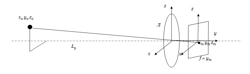
Figure 3 - Transformation of coordinates of the object optical system of cameras
The basic coordinate system is located in the center of the optical system (lens A). The flat image of the object is formed in the frame of the matrix, which is the result of parallel transport of the main system at a distance of ym.
The original image of the object with a set of coordinates of all its points x0, y0, z0 is transformed into an optical system with a flat image coordinates of the points xm, ym, zm in ym≈f (the object is located at a distance Ly >> f).
In accordance with the laws of geometrical optics relationship between the coordinates of a flat image of the object on the sensor and the actual coordinates in the space defined by the relations:
.jpg)
The distance to the object Ly:
.jpg)
5. The algorithm for finding the coordinates of a bright light source
To determine the coordinates of a bright light source can offer the following algorithm for image processing:
- Increasing the contrast processed images using the spectral differences between the background and the object.
- image filtering to suppress the background and noise. Removing the background leads to a reduction in processing time and improve accuracy of video detection of objects within the scene. In the special case of a stationary video camera with a fixed field of view, the so-called static background can be estimated quantitatively. In general, the name "static background" arbitrary, since the brightness distribution in it is constantly changing and for the proper selection of moving objects is required to periodically re-evaluated. Background score is necessary because the background is constantly changing due to the change of light, noise background image, the emergence in the field of foreign objects [3].
- Isolation bright light source. Isolation of bright objects and the suppression of the stationary background in the image plane can be done using a simple difference algorithm, but it is susceptible to changes in the brightness of the background and objects and features a large resource consumption.
- Isolation of the image-related areas of increased brightness (segmentation of objects). After selecting the image areas with high brightness, their segmentation is performed, allowing an object to form a single image, characterized by a certain shape and size. Blocks belonging to the same object should be placed on the frame in one area and form a related group.
- Determination of coordinates of the center of gravity of the object:
To implement the algorithm that determines the coordinates of a bright light source, the current frame is divided into rectangular blocks of equal size, and for each block compute the greatest difference from the previous frame. As a measure to calculate the sum of absolute differences of the difference of brightness of pixels within a block of MAD [6]:
.jpg)
where m, n - the number of pixels in the block.
.jpg)
Conclusions
- to protect against glare overlapping bright light source can be achieved by the introduction of an opaque barrier, overlapping part of the review.
- The algorithm of image processing, allowing to determine coordinates of a bright light source. This algorithm does not have much time-consuming, since the problem does not need to process high-resolution images. The above algorithm is required for software development of automated control systems by means of protection from glare.
- Manage Your remedy will be implemented using microcontrollers.
- Use of this device will allow, without noticeable loss of quality indicators of visibility, visibility, color and contrast of the objects observed to reduce the adverse effects of excess light energy in the bodies of people, reduce fatigue and increase productivity.
In writing this essay master's work is not yet complete. Final completion: December 2012. The full text of the and materials on the topic can be obtained from the author or his head after that date.
Список источников
- Повышение точности центроидного алгоритма для определения координат малоразмерного объекта [Электронный ресурс]. – Режим доступа: http://lib.tusur.ru/cgi-bin/....
- В.В. Коротаев. Телевизионные измерительные системы: учебное пособие. / В.В. Коротаев, А.В. Краснящих. – СПб: СПбГУ ИТМО, 2008. – 108 стр.
- Телевизионные измерительные системы контроля скоростного режима дорожного движения [Электронный ресурс]. – Режим доступа: http://www.kit-e.ru/assets/....
- Европа за здоровых сварщиков: Средства защиты [Электронный ресурс]. – Режим доступа: http://uraltreid.ru/....
- Средства защиты сварщика [Электронный ресурс]. – Режим доступа: http://www.svarkainfo.ru/...
- Метод определения координат транспортных средств на изображении в телевизионных измерительных системах [Электронный ресурс]. – Режим доступа: http://www.rae.ru/...
- Маски Speedglas [Электронный ресурс]. – Режим доступа: http://www.msvarki.ru/welding/?data_id=135/