Computer System for identifying defects in plates JSC "Donetskstal MZ"
Автор: Bobylev S.S., Adamov V.G.
Автор: Bobylev S.S., Adamov V.G.
Bobylev S.S., Adamov V.G. Computer System for identifying defects in plates JSC "Donetskstal MZ". The article deals with the diagnosis of damages of rolled sheet, namely pitting, blistering, and then using a computer system in JSC "Donetskstal MOH." The problems of structural design and concept of computer control system of surface defects in metal. The issues of improving the quality of the studied images using median filtering and the use of a linear contrast.
Increased demands on the quality of metal lead to the need for the development of modern methods and means of monitoring the surface of flat rolled products.
Detection of defects requires more effort. In February 2010 compared with January 2010, the percentage of processing sheets to identify the damage on the steel I-st and II-th redistribution of JSC "Donetskstal MZ" increased from 37.5% to 41.3% [1].
The introduction of automated quality control devices, which replace the visual inspection can reduce the reject rate of products, provide more effective control. The process of diagnosing the quality of the surface of the sheet metal consists of a sequence of operations on the digitized image:
• detection of defective areas with pre-treatment study images using median filtering and the use of a linear contrast;
• determination of the physical characteristics of the surface defect (size, shape, color, location);
• classification of surface defects.
The main objectives of the study are:
• Development of structural concept and the computer control system of surface defects in metal;
• Addressing the problem of detection of pores and bubbles on the metal plates;
• Pretreatment of study images using median filtering and linear contrast;
Based on the output report [2], following the analysis of the process, in a scientific paper [1] have been developed and describes the basic components of a computer control system of surface defects in metal.
These studies have allowed us to develop a principled and structured scheme of computer control system of surface defects in metal.
Fig. 2 shows a schematic diagram of a computer control system of surface defects in metal. The scheme includes the following elements: the camera unit, the unit lighting system, power subsystem capture a frame, a block of the processor, the display unit. Lighting unit is required to maintain the level of brightness, lighting the surfaces to be inspected. The resulting image is passed to block frame grabbing subsystem, which is used to convert analog video to digital form. Processor unit performs pre-processing algorithms for digital images – filtering and contrast, counts of surface defect characteristics (size, location), performs the detection of defects. The display unit for displaying the results to the user defects.
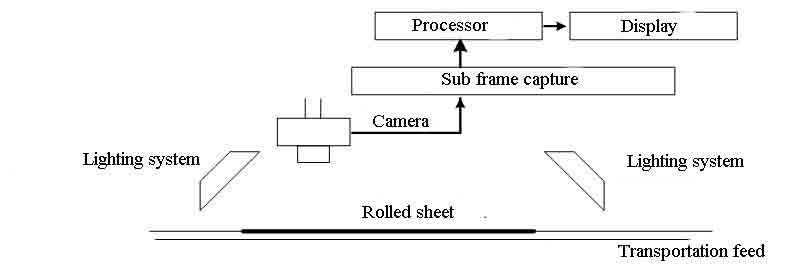
Fig. 1 – Schematic diagram of a computer control system of surface defects in metal
Fig. 2 shows a block diagram of a computer control system of surface defects in metal. The block diagram of a computer control system defects of metal designed to perform the following tasks: data entry, image preprocessing, identification of defects in the picture, classification of defects.
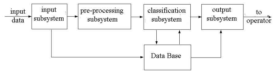
Fig. 2 – Block diagram of a computer control system of surface defects in metal
One of the most important and intractable problems to date, poor quality of his images are noise and low contrast.
Sources of noise may be different: imperfect equipment for image capture, poor shooting conditions – such as loud noises that occur in low light, noise in the transmission of analog channels – interference from sources of electromagnetic fields, the intrinsic noise of the active components (amplifiers) transmission line.
Noise reduction algorithms tend to specialize in the suppression of a particular type of noise. There is still the universal filter, detecting and suppressing all kinds of noises. However, many noises can be quite well approximated by white Gaussian noise model, so most algorithms focused on the suppression of this type of noise.
The most appropriate method of filtering Gaussian noise was median filtering.
For each pixel in some of its environment (window) is sought, and the median value is assigned to a single pixel. Determination of the median: if an array of pixels sorted according to their value, the median is median element of the array. Median can also be defined by the formula:

where W – the set of pixels, of which the median is sought, and fi, fj – brightness values of pixels.
For color images using vector median filter

where fi, fj – pixel values in the three-dimensional color space, and d – an arbitrary metric.
There have been machine experiments in MATLAB to determine the effectiveness of the proposed method of filtration. Fig. 3 shows the results of the filter median filter.
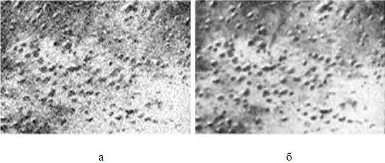
Fig. 3 – The output of the filter median filter a) noisy image (Gaussian noise), and b) filtered image
The problem associated with improved contrast matching the dynamic range of images and the screen on which the visualization.
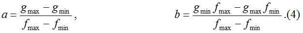
Increase the contrast of the image allows the application of the method of linear contrast, when the brightness of each pixel is recalculated so that the brightness range of the original image [fmin, fmax] to stretch the range of brightness [gmin, gmax]:

where g – output pixel brightness; f – the original brightness of the pixel; a, b – coefficients of the transformation. The parameters of this transformation of a, b can easily be determined on the basis of the required changes in the dynamic range. If the processing needed to get the scale [gmin, gmax], then
There have been machine experiments in MATLAB to determine the effectiveness of the proposed method contrasting. In Fig. 4 shows the results of the linear contrast.
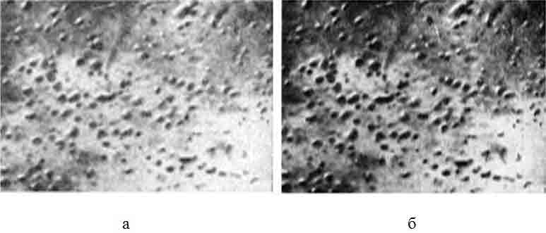
Fig. 4 – The output of the linear contrast a) filtered image, b) filtered image with high contrast
Studyed pictures of images showed that the location of defects differ from the rest of its surface brightness characteristics. In the picture they have a darker shade. So far the process of finding and bubbles associated with the calculation of the appropriate threshold value image (grayscale). This threshold depends on the imaging system and must be configured on the camera position and lighting. In [3] presented a method to Burns.
For each pixel (x; y) is selected brightness threshold

where Bmax,Bmin – respectively, the highest and the lowest brightness level of pixels of a square neighborhood of pixels (x; y). If the level of contrast (the difference between the highest level and the lowest levels) exceeds a certain threshold, the pixel is either white or black. For all images the threshold contrast is constant and must be selected interactively.
Machine performed experiments to determine the effectiveness of the proposed method. As a software package was used environment for analysis, modeling and design of MATLAB. In Fig. 5 shows the results of computer simulation.
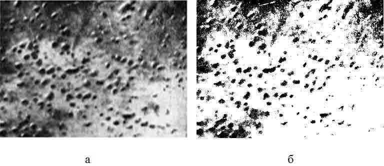
Fig. 5 – The result of the detection algorithm and then bubbles a) The original image is processed, and b) binary image
To solve this problem was developed by the structural and schematic diagram of a computer control system of surface defects in metal.
Implementation of the proposed project will improve productivity, reduce time to process information.
1. Bobylev, S.S. Detection of damage rolled sheet in CJSC "DMZ" by means of a computer system / S.S. Bobylev, V.G. Adamov. – Donetsk: 2010. – p. 70–74.
2. Output report: "Analysis of the nature of surface defects on steel I-st and II-th redistribution metallographic laboratory control of CCL Donetskstal 2009", 2009.
3. Gonsales, R. Digital Image Processing / R. Gonsales, R. Woods. – 2005. – 1072 p.