Fig. 1 – A scheme of interaction of a set of simulation processors (SimProc) with a simulation process administrator (SPA)
Source: http://sim.1024.info/text/science/20041023.html
Y.V. Popoff. A program system for distributed event-driven logic simulation. Algorithms for experimental research of parallel simulations are developed. A system architecture is proposed. Analysis of synchronization protocols for logic simulations is fulfilled. Software was implemented and tested in a local network.
Project verification is an important stage in creating of electronic designs. Executing of simulation process is an effective way to verify if an electronic device operates correctly. The purpose of simulation is both a functional project verification and time analysis of device behavior. Simulating systems with high complexity and large parameter spaces require tremendous computational and memory resources. Hardware accelerators perform simulation processes much faster then usual computers. But hardware accelerators are much more expensive also. Accelerating of simulation may be obtained by implementing of a simulation model on a computer network.
An object-oriented analysis of simulation algorithms have been performed to implement a program system for distributed event-driven logic simulation. Special technologies for gathering and analysis of distributed simulation results have been implemented in the program system.
Goals and tasks of the research include analysis of distributed simulation algorithms and showing up peculiarities of an implemented program system based on experimental data [3,4].
The software system for distributed event-driven logic simulation is consists of three subsystems: a subsystem to prepare input data for simulation processors, a simulation subsystem and a simulation results analysis subsystem.
Current implementation of simulation algorithms allows to simulate digital devices. A simulation alphabet and a set of elements used in the circuit are defined by a set of dynamic libraries (DLLs) used and can be extended by adding new DLLs.
The subsystem to prepare input data for simulation processors contains following program components. Each component is a separate Windows executable:
ISCAS89 to SSM format converter. SSM is a special file format that contains description of a circuit. This format is used in the current implementation of simulation processors;
multilevel visual circuit editor. This editor allows to create new elements. Behavior of these elements is described by a truth table or may be inherited from another circuit. These elements can be used to create new circuits. Special DLLs can also be used as circuit elements;
partitioner – partitions a circuit into parts. Each part is simulated on a separate simulation processor;
random circuit generator – allows to generate random circuits. A special file called «circuit generator project» describes a set of parameters of a circuit to be generated;
stimulus editor – is a visual editor for stimulus;
random stimulus generator – to generate random stimulus. A special file called «timulus generator project» describes a set of parameters of a stimulus to be generated.
Source data for simulation processors is a stimulus file and a set of SSM files. These files have simple text format. Any set of programs can be added to the system to generate, manage and prepare these files for simulation processors.
A simulation subsystem contains following program components:
a set of simulation processors (SimProc). Simulation processor is an implementation of a simulation algorithm. Each simulation processor is running on a separate computer;
simulation process administrator (SPA) – is a special program running on a separate computer.
A scheme of interaction of a set of simulation processors with a simulation process administrator is showed in fig. 1. A local area network is used to communicate SPA and SimProcs.
Fig. 1 – A scheme of interaction of a set of simulation processors (SimProc) with a simulation process administrator (SPA)
Simulation of a single circuit partitioned in some parts, with a single stimulus and an exact set of simulation parameters is called simulation task. Each simulation task requires as many simulation processors as many parts in the circuit. SPA project contains description of a set of simulation tasks.
SPA project is loaded into SPA. SPA distributes simulation tasks between SimProcs. If free SimProcs available in the system, then some simulation tasks could be processed simultaneously. SPA sends commands to SimProcs to load circuits, load stimulus, set some simulation parameters.
Each SimProc writes a simulation log while simulating a task. The simulation log is written into a local file. Simulation log contains information about messages sent/received from a network, about events processing, system state modifications and internal method calls. SimProcs may send simulation logs to SPA. This allows to gather simulation logs from all SimProcs into a single file. This feature is only used when simulating small circuits with short stimulus with conservative synchronization protocols or with an optimistic synchronization protocols with a small degree of optimism; greater circuits/stimulus or optimism degree may produce simulation log files with size of hundreds of megabytes. However, information written into a simulation log may be restricted. For example, we may only log output nodes values. In such case the simulation log will not be so huge.
Example of SimProcs and SPA forms is presented at fig. 2. These applications have simple user interface. This is done to allow to recompile these applications for another platform or operating system more easy. The whole control over SimProcs and SPA is performed by using SPA projects.
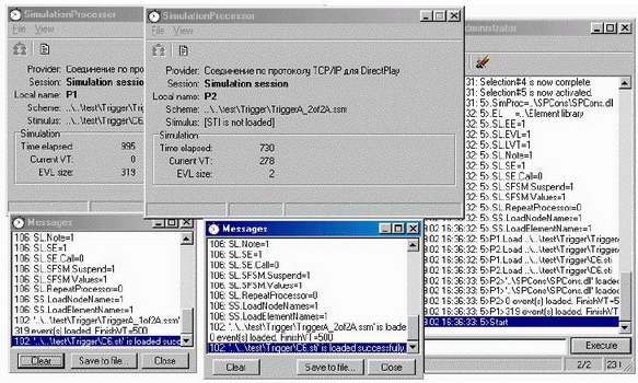
Fig. 2 – A program system for distributed event-driven logic simulation
Following simulation algorithms have been implemented [1,2]:
a sequential simulation algorithm. The whole circuit is simulated on a single simulation processor. Events are executed one after another;
a distributed asynchronous simulation algorithm with a conservative synchronization protocol. Deadlocks are allowed in the system. A deadlock resume algorithm with a marker is implemented to resume system from deadlocks. A prediction algorithm with null-messages is also implemented;
a distributed asynchronous simulation algorithm with an optimistic synchronization protocol. A limited optimism techniques is used to avoid unlimited growth of erroneous events in the system. A lazy cancellation algorithm is implemented to cancel straggler events. Only modified state variables are stored in the state stack to save some memory.
The result of the simulation is a file with a simulation log. Simulation log is written in a special language, called a language of cause-and-effect relations diagrams (CER-program). CER-program allows analysis of a simulation process.
A simulation results analysis subsystem contains following program components:
a program to build waveform diagrams;
a program to build cause-and-effect relations diagrams (CER-diagrams) (fig. 3);
a program to gather statistical information about simulation process.
The purpose of CER-diagrams is a visual simulation process representation and research of synchronization protocol behavior features. CER-diagram (fig. 3) contains a list of state variables for every simulation processor (for example, signal values in circuit nodes and LVT), messages transferred over a network; actions performed by simulation processors (for example, event processing and event generation), physical timestamps.
Fig.3 – A cause-and-effect relations diagram example with comments
Using distributed computations is an important way to accelerate simulation processes.
The program system implemented allows to research synchronization protocols used in distributed event-driven logic simulation. Detailed research of CER-diagrams allows to determine peculiarities of an implementation of a synchronization protocol. A distributed applications debugging technology is developed.
Following topics is of a special interest for further research:
implementing of dynamic load balance techniques;
detailed research of partitioning algorithms;
developing and executing experiments to research an implementation of synchronization protocols;
developing a web-interface to allow access to a distributed simulation system from Internet;
implementing an application that allows to simulate systems regardless it is a digital device or not.
1. Chandy K.M., Misra J. Asynchronous Distributed Simulation via a Sequence of Parallel Computations. Communications of the ACM, 24(11): 198-206, November, 1981.
2. Ferscha Alois. Parallel and Distributed Simulation of Discrete Event Systems. In Hardbound of Parallel and Distributed Computing. McGraw-Hill, 1995.
3. Ладыженский Ю.В., Попов Ю.В. Система распределенного логического моделирования цифровых устройств с использованием консервативного протокола синхронизации // Наукові праці Донецького національного технічного університету. Серія: інформатика, кібернетика та обчислювальна техніка, випуск 39: - Донецьк: ДонНТУ, 2002. - 282 с. – с. 21 – 29.
4. Ладыженский Ю.В., Попов Ю.В. Объектно-ориентированная модель протоколов синхронизации при распределенном логическом моделировании цифровых устройств // Наукові праці Донецького національного технічного університету. Серія: Обчислювальна техніка та автоматизація. Випуск 64. – Донецьк: Вид-во ДонНТУ, 2003. – 280 с. – с. 212-221.