Digital Direction Finder DDF 190
Author: Franz Demmel; Ulrich Unselt
Источник:
News from Rohde & Schwarz
(1996) No. 152, pp 30 – 32
Режим доступа: rohde-schwarz
Author: Franz Demmel; Ulrich Unselt
Источник:
News from Rohde & Schwarz
(1996) No. 152, pp 30 – 32
Digital Direction Finder DDF 190 [*] was originally designed for the VHF – UHF frequency range covered by the two DF Antennas ADD 190 (20 MHz to 1300 MHz) and ADD 071 (1300 MHz to 3000 MHz) (Fig 1). In response to the great success of this DF family and the requests of many customers for a favourably priced and compact DF solution in the HF range too, Rohde & Schwarz has extended the direction finder accordingly.
What is most conspicuous is the new HF DF Antenna ADD119 that covers the frequency range 0.5 MHz to 30 MHz. Extended ware in DF Unit EBD190 performs bearing calculations in this range. Connection Board GX190 is responsible for auto-matic selection and power supply of the antennas, which may also work simultaneously. DDF190 offers full remote control via the RS – 232 – C system interface of EBD190 in the extended frequency range too.
Even in the shortwave range, Direc-tion Finder DDF190 can work with all receivers featuring an unregulated IF output of 10.7 MHz or 21.4 MHz, for example broadband Rohde & Schwarz receivers EB200 (FIG 1) or ESMB, or ESMC plus Frequency Extension ESMC – FE. Test receivers can also be used of course, for instance those of the ESN or ESVN series.
In the VHF – UHF range, the direction finder operates on the principle of a cor-relative interferometer which, thanks to a patented Rohde & Schwarz method, requires only one receiver instead of the two of a conventional system. The Watson – Watt method employed in the HF range allows the use of very compact antennas.
HF DF Antenna ADD119 consists of two crossed, active loop elements and an active dipole housed in a flat, fiberglass – reinforced plastic radome. It permits direction finding with a maximum error as small as 2° (rms), allowing ITU class A to be attained also in the HF range assuming an environment with suffi ciently low interference, adequate S/N ratio and vertical polarization. The directional patterns of the antenna elements make ADD119 suitable for receiving groundwaves as well as flat skywaves. To obtain unambiguous bearings, the mast height should be no more than about 20 % of the shortest operating wavelength – higher masts, because of their self – resonance, lead to unduly large phase differences between the loop and dipole elements and thus to ambiguous results. ADD119 has the same size and connectors as VHF – UHF Antenna ADD190 and is ideal for mobile and stationary applications.
Fig 1 shows a typical system configuration for mobile applications in the HF and VHF – UHF ranges. Antennas ADD190 and ADD071 are mounted on a telescopic mast attached to the vehicle. To minimize mutual interaction, HF Antenna ADD119 is set up on a tripod at a distance of about 40 m. ADD190 and ADD119 can betted with an electronic compass (option) for automatic north alignment.
To congure a system with only one mast – for example in stationary appli – cations – with ADD190 mounted at the top of the mast, the disturbing effect of the mast in the HF range can be eliminated by using two Antennas ADD119 on opposite sides of the mast in conjunction with Combiner GX119.
Connection Board GX190 comprises a control – signal distributor plus an RF selector for 0.1 MHz to 3000 MHz,
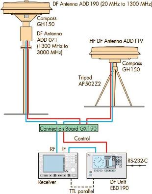
Fig. 1 Typical configurarion of mobile DF system for 0.5 MHz to 3000 MHz
which connects one of maximally six antennas to the output. This is usually done by automatic control from DF Unit EBD190, but the system can also be configured for control via an RS – 232 – C interface.
DF Unit EBD190 comes with a front panel keypad and LC display for convenient, straightforward operation. The receiver is operated separately; interfaces for antenna range selection are supported however. Sequential scanning of the antenna elements during the DF process leads to noise in the AF signal of the receiver typical of single – receiver direction finders. For undisturbed monitoring of the useful signal, the scanning function and thus direction finding can be switched off (AF/DF key).
1. Demmel, Franz; Wille, Raimund: Digital direction finding from 20 to 3000 MHz to ITU guidelines. News from Rohde & Schwarz (1996) No. 152, pp 30 – 32