What happens when doppler RD Fing and digital processing get together?
Author: Joe Moell P.E.
Источник: PO Box 2508 Fullerton, CA 92837
Режим доступа: homingin.com
Author: Joe Moell P.E.
Источник: PO Box 2508 Fullerton, CA 92837
"It's a fast track into T-hunting!" That's how one ham describes doppler radio direction finding (RDF). Because dopplers attach to ordinary mobile or hand-held FM transceivers and require no rotating parts or holes to be drilled, you can join the hunt in minutes, even in a rental car.
Doppler RDF sets are easily identifiable by their array of three to eight vertical whip antennas. A switching circuit electrically connects the whips to your receiver one at a time in rapid sequence to simulate a single whip moving in a circular pattern. Due to a property of physics called the Doppler Effect, this apparent motion of the receiving antenna applies periodic frequency modulation to incoming signals. The display unit detects the phase of this imposed FM with respect to the antenna switching sequence. This tells the direction of the signal relative to your vehicle heading. Because the simulated rotation rate is about 30,000 RPM, dopplers can capture bearings on signals lasting only a fraction of a second.
If your RDF need involves the DX bands (below 50 MHz), very weak signals, or signals with no carrier such as single-sideband voice, forget about using a doppler. It is also not a good choice if you will be doing your tracking on foot. If you want to do RDF remotely from a mountaintop radio site or go after horizontally polarized signals, there are more effective methods to consider. But if you want to go mobile to quickly find a strong VHF-FM or UHF-FM hidden transmitter, spurious signal or jamming station, a doppler may be just the right tool for you.
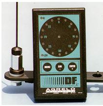
Fig. 1 Alegro DF system
Until recently, you had the choice of spending at least $600 for a commercial wired/tested doppler set or building your doppler at home for about $150 plus hours of parts gathering and construction. Now there is an attractive third option, the DFjr by Agrelo Engineering. It is not a kit, but a complete plug-and-play RDF add-on for 120 to 550 MHz, made in the USA and selling for about $350. Your only assembly tasks are mounting whips and magnets onto the antenna unit frame and installing the system on your vehicle.
The DFjr display box (photo above) measures only 2-3/4 X 4-1/2 X 7/8 inches. It's so small that I misplaced it a couple of times before I got it installed in the van. There are no protruding switches or knobs, so it fits nicely in a shirt pocket. You might think that it could be mounted anywhere in a vehicle, but there are practical limitations. You can't just place it atop the dashboard, because all connectors are on the bottom edge. You need to find a shaded spot that is easy to view by driver and assistants. Provide a solid backing so you can depress the three buttons firmly. For me, the best solution was making a pair of aluminum strip brackets to span between the heater duct and the instrument cluster. Velcro[R] strips hold the DFjr to the brackets.
Any function operation on the DFjr requires pressing sequences of one or more of the three membrane buttons on the panel. The manufacturer says that these switches require only 100 grams of force, equal to the weight of three parakeets. But in my tests, the center button required 500 grams and the two edge buttons needed almost a kilogram to actuate. Some users have told me that they miss the positive tactile feel of ordinary pushbuttons. I agree and I would also like to have a digital readout or auditory feedback to indicate what modes have been selected.
The display box has no room for a speaker. Most users plug the DFjr into the receiver's external speaker jack and plug an external speaker into a jack on the DFjr. The alternative is rewiring your radio's external audio output jack so it doesn't cut off the radio's speaker. Agrelo provides the audio cable from radio to DFjr, but not an external speaker or its cable. Audio plugs and jacks are 1/8 – inch connectors, not the more widely used 1/4 – inch types. There is no power on/off switch. I got tired of pulling out the 12 – volt DC connector sandwiched between two audio cables on the bottom edge, so I bought an in – line switch from a hardware store and installed it in the cable.
The DFjr has a traditional circular directional display of sixteen light-emitting diodes (LEDs). There is a green LED in the center of the circle, making it easier to interpret the readings in a dark car at night. Red HI and LOW LEDs help you set the audio level from your receiver. The LED indicating low level must be off for the unit to process bearings. Occasional flashing of the HI level LED is OK, but too much audio will make it come on continuously and performance may suffer. When doppler tone falls below threshold level, the display automatically holds the last bearing.
As with other dopplers, you should recalibrate the display electronics each time you change receivers, vehicles, or ham bands. There is no rotary calibration control; you press all three buttons simultaneously when the target signal is known to be dead ahead. A parenthetical note to readers who wonder why not calibrate by having someone stand directly in front of the car with a keyed hand-held: You probably will not get a highly accurate calibration on any VHF doppler set that way, due to near-field multipath and a non-planar wavefront. It is much better to be driving toward a known-location signal such as a repeater or NOAA weather station. Better yet, have a fellow ham transmit while driving several car lengths ahead of you as you move along with your doppler setup.
To go with its novel display unit, the DFjr includes a complete easy-to-install mobile antenna system. Its aluminum crossarm frame has twelve holes so that whips can be quickly and accurately positioned for the two-meter, 125 cm and 70 cm bands. (Corner-to-corner spacing of the four-whip footprint must be between one quarter and one half wavelength for proper doppler operation.) The switcher consists of four monolithic RF preamplifiers and switching transistors in a weatherproof enclosure at the center of the array (interior photo at right).
The original antenna set (partially shown in Page 1 photo) had one large magnet directly under the switcher box. Early users quickly discovered that this design was unacceptable. The lack of a counterpoise for each whip severely degraded RDF performance. When four magnets on "pigtails" were added to RF-couple the coax shields to the car roof at the base of each whip (antenna Version 2), performance improved markedly.
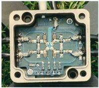
Fig. 2 Arrangement of elements
Agrelo's staff redesigned the array to have four fixed magnets, one under each whip (photo at left below). Many of these Version 3 sets worked well, but some developed shorts at the whip bases. In my case, shrink-sleeve tubing covering the crimp portion of a solder lug cold-flowed to create a low-resistance condition that made the display "wander" randomly. The problem was not detectable with an ohmmeter, but I could observe differences in pulse waveforms on the whips with an oscilloscope. That antenna version has chrome plated hex upper nuts and black whip-holding caps with hex-head setscrews. If you have one, I recommend that you add tape or other insulation at the crimp ends of the lugs at the whip bases to avoid shorts.
Shorting problems have been solved in the latest antenna set (Version 4) being shipped to new buyers (photo on next page). It has a plastic coax termination at each whip and conical upper nuts with slot-head setscrews. An instruction sheet with eight color photos shows you how to put it together. The four mag-mounts are high quality with rubber padding to protect your vehicle finish. Unless you have a non-metallic or deeply corrugated rooftop, installation will be a snap. (Four snaps, actually.)
The Version 4 antenna set has a 12-foot data (RJ-25C) and RF (RG-58) cable, enough for sedans and trucks. I prefer to mount the antenna set at the rear of my minivan roof. The cables are about three feet too short for that. Extension cables are available from Agrelo Electronics, or you can make your own.
While any doppler RDF set can be modified for computer interface by adding a serial communications board, the DFjr is computer-ready right out of the box. Its RS-232 serial port feeds relative bearing information at one of five selectable baud rates. You can program it so bearings come out of this port only when their quality is above a desired threshold. With Agrelo's optional Multi-Port Adapter (MPA) accessory, a laptop computer, packet terminal node controller (TNC) and separate VHF-FM transceiver, you can transmit your position and RDF bearings via Automatic Packet Reporting System (APRS). You can also display the bearings of other similarly-equipped T-hunters in the APRS network on your laptop.
The MPA combines RDF and Global Positioning System (GPS) data onto one computer port. The rate at which your position and RDF bearings are transmitted on packet can be selected from 5 second to 16 minute intervals, or entered manually by pushing two buttons on the DFjr. While your setup transmits packets, the DFjr automatically halts RDF processing, avoiding bearing errors due to QRM from your packet transmitter.
Besides the DFjr's miniaturization and plug-and-play attributes, Agrelo Engineering touts its "smart" processing. The manual states, "Although no unit can eliminate multipath and signal dropout, the DFjr simply ignores the effects."
In point of fact, no VHF RDF set, doppler or not, can ignore multipath. Let's say you are parked along a road through a canyon and the target station is over a hill to your left. The direct signal is greatly attenuated by knife-edging over a ridge. At the same time, this signal is being reflected toward you from a hilltop in another direction. This condition – signals from the same source arriving via more than one route – is the definition of multipath.
If the reflected signal in this case is stronger than the direct signal, your doppler will either indicate that the signal is coming from the hilltop (an erroneous bearing) or it will show a "wild" bearing between the two signal sources. If you and your doppler begin moving under these same conditions, the relative strengths and phases of the direct and reflected signal components will change continuously at your antenna, making a traditional doppler display flicker, jump and "dash around the ring."
By narrowing the bandwidth of the tone filter in a traditional doppler processor, jumps and flickers are reduced substantially, but there are practical limits to this technique. Doppler users "eyeball average" the dancing display to deduce their best estimate of the true direction of the signal source. This technique works for experienced T-hunters in most situations, but if there is insufficient direct signal relative to one or more very strong reflections, no amount of "brain processing" will turn bad bearings into good ones.
The DFjr has two operating modes. In the Raw Mode, bearings are displayed in real time with moderate tone filtering, just as in traditional dopplers. In the Statistical Mode, the DFjr accumulates samples for approximately two seconds, digitally processes them with a proprietary algorithm and then displays the resulting estimated bearing.
The garbage-in/garbage-out principle applies to the Statistical Mode. If your vehicle and the target emitter are stationary, and if there are no moving reflecting objects in the signal path, all sample data points will be alike and there will be no difference between Raw Mode and Statistical Mode indications. If you are moving in a straight line and enough good data can be captured in the sampling period, a good processed bearing will result. But when you are in an area where most or all of the incoming signal is reflected (It happens!), no amount of statistical analysis will turn two seconds worth of bad data points into a good bearing. Furthermore, if your vehicle turns sharply or if there is more than one signal received in the sample period, the calculated bearing is meaningless.
I have used the DFjr for several months, taking lots of test bearings on stations in known locations and going on competitive T-hunts hidden by very clever hams. I find that I frequently change from Raw to Statistical mode and back again, just to get a "feel" for the RF environment where I am at the moment. In the Statistical Mode, a new bearing appears about every two seconds, sometimes 180 degrees from the last. It makes me wonder, "Did I pass the hidden T or am I being deceived by multipath again?" With lots of tall buildings, canyon freeways and mountain peaks within our T-hunt boundaries, severe multipath is a way of life in southern California. Some T-hunters claim there is no place in the USA where it is worse. It takes time to learn to use any doppler in this environment. If you are like me, you won't win your first strong – signal T – hunt with your DFjr, but you will eventually find the transmitter, or at least get as close as you can by road. Your skill will improve as you gain experience, just as it does with any other RDF method.
When describing measurements, it is common for the terms "accuracy" and "resolution" to be confused. DFjr's advertising is a case in point. The Agrelo Web site states that the DFjr has +/- 1.40625 degree accuracy in the Statistical Mode. Don't take this to mean that your bearings will always be within a couple of degrees. That number is not the RDF accuracy, it is the resolution of the digital output from the RS-232 data port.
In the data output, the 360-degree azimuth range is described by 256 bits, each bit representing about 1.4 degrees. Format is "%xxx/y" where xxx is the relative bearing rounded to the nearest degree and y is the quality of the bearing. Quality is a computed function of the spread of the data points in the sample period and ranges from 1 (worst) to 8 (best).
Even if you could perfectly calibrate a doppler and even if there were no such thing as multipath, +/- 1.4 degree bearing accuracy over the 360-degree range is not a reasonable expectation, due to factors such as mutual coupling among whips in the antenna system. Tests by a maker of VHF doppler sets for the military a decade ago showed that sophisticated 4-whip dopplers were capable of only about +/- 5 degrees accuracy under ideal conditions, no matter how good their resolution.
Steve Hall KK4PM performed accuracy tests of his DFjr on known – location repeaters last summer and reported his results to the APRS Internet mailing list. He wrote a computer program to automatically compare his field bearings from the DFjr data port to GPS-computed headings from his field locations to the repeaters. Sure enough, Steve found that computed accuracy was about +/- 5 degrees when he was driving in the clear and worse in areas of high signal reflections.
If your DFjr is not connected to a computer, your bearing indicator is the 16 – LED doppler readout, which provides only +/- 11.25 degree resolution. While not good enough for precision triangulation, it's fine for homing in on a hidden transmitter in a mobile T-hunt. Just let the display lead you down the roads.
T – hunting is not an exact science. Every hunt and every hunter is different. Most hunters' judgment of their DF gear is subjective, based on their own experiences. With that in mind, I have talked to numerous hams about their DFjr results in actual RDF activities and I've gathered a wide variety of responses. Some hams, like J. Scott Ratchford KC5JGV of Marshall, Arkansas, are very enthusiastic.
"We don't have any competitive T-hunts in this area right now," Scott says. "My main interest in the DFjr was to use it with APRS, because that gives me the graphical readout that I was looking for. I don't usually transmit my position, because my digipeater is 40 miles away. I'm a one-man operation and I have all my computer gear in the passenger seat of my Blazer. When I'm not avoiding the ditches and trees, I'm looking at it. Joe Agrelo has been very helpful with my APRS interface. I have received three firmware upgrades from him.
"We've got lots of rolling hills around here and a few cliff faces that are pretty sheer," Scott continues. "Signal reflections are pretty obvious when you're in the hills because the display will indicate that the signal is coming down the highway toward you, then you will come to a little opening and suddenly it appears to be coming from the side. Every once in a while this can really screw you up. I usually use the Raw Mode. I listen very closely to the speaker and can tell when the signal is being bounced by the sound, it sounds as if it shifts to a higher frequency. When it's dead on, I get a solid tone.
""Last summer, I used the DFjr to help a stranded ham who was canoeing on the Buffalo River," says KC5JGV. "His canoe had turned over, he and his wife were in the water, lost and looking for help. I guess you could say he was literally up the creek without a paddle. Fortunately, it wasn't too serious because we don't have a lot of water in the river in July, but his wife was mad and he wasn't very happy. I was monitoring 146.52 and heard him call out. I got a pretty good fix with the DFjr and APRS display. He told me that he wanted to go to a takeout point at the Highway 14 bridge. I was able to tell him that he was only about a half mile from his destination. It all turned out OK."