
Abstract
Content
- 1. Relevance of the topic
- 2. The aims and objectives of the study, the expected results.
- 3. Review of research, the expected results.
- 4. The presentation of the material.
- Conclusions and directions for further research.
- References
1. Relevance of the topic
At present, the extent of supported mine workings reaches 199.5 km/Ma. tons of coal produced. In this case the length of the workings contained supple lining and arch are in poor condition, reaches 17.5 %. This is due primarily to insufficiently high bearing capacity of roof support frame and the discrepancy between the existing parameters of mining-geological conditions.
2. The aims and objectives of the study, the expected results.
It is clear that to improve the stability of the excavation and the duration of their need to eliminate the existing shortcomings of attachment. You can change the situation through the use of anchoring. Therefore, actual scientific task is to conduct research aimed at studying the behavior of the rock mass, the combined fixed frame and roof bolting, to further establish rational parameters of its maintenance, which provide a reduction in the displacement of host rocks.
3. Review of research, the expected results.
To date, there are many scientific and technical literature, which reveals the mechanism of interaction between different types of attachment to the rocks surrounding the production. The main sources of research can be identified A.P.Shirokova V. Vinogradov, V.T.Glushko, A.A.Borisova, N.I. Melnikova, L.M. Erofeev, A.N. Zorina, I.A. Kovalevskoy, B.K. Chukuna, A. Remezov, I.A. Yurchenko, A.N. Shashenko, A. Yugona, A. Kosta etc.[1-22]
In general, these works allow you to select five theories of anchoring: the immediate suspension of the roof to the main load-carrying structure formation, compression, supporting rock, collaboration, and rock bolting, the energy theory. But after analyzing them, there are three main areas of interaction of the combined frame and roof bolting, and the array:
- First line describes the roof bolting, reinforcing the frame as an additional structure. In the calculations of the expected displacement of the rock surrounding the mine workings, is used which reduces the coefficient, which depends on the density of anchor installation.
- The second line describes the interaction between frame and amplifying it, roof bolting, as a single load–carrying structure. In this case the parameters are chosen taking into account the expected displacement of the contour floating production, as well as geological and mining conditions.
- The third line describes the interaction between frame and roof bolting as a single connected structure. Here the basic parameters of such structures are calculated theoretically using the forces.
Improving cooperation issues framed and roof bolting is to study their effects on an array of
host rocks over time. One of the promising ways to solve this problem is to establish the
distribution of loads, which are perceived by the individual constituent elements of the
mounting frame – the shell of the fortified rock.
This, in turn, will better calculate
the parameters of the combined lining.
In this context, the purpose of this paper is to establish patterns between the increase in roof support frame anchors, and the process of forming zones in the mountain massif broken rocks (ZRP).
4. The presentation of the material.
Investigation of the influence of gain–frame roof support anchors in the process of forming zones around the development of the destroyed rocks was carried out with 12 models of equivalent materials. It was used two types of mixtures: gypsum sand and paraffin–sand. Layout and production of frames in the models and the general characteristics of models are presented in Figure 1
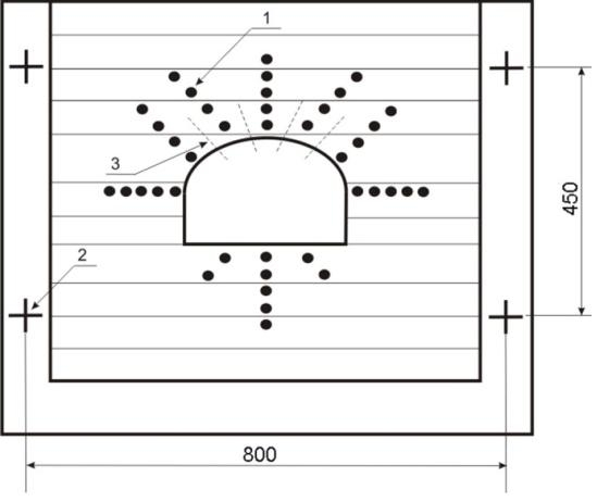
Figure 1. Shema location and production frames in the models of equivalent materials.
Studies were performed in the following order. Initially, determined the final displacement and the size of ZRP in an array corresponding to the mining–geological conditions and fixed frame supple lining. Then, in similar conditions simulated output, which after the implementation of a given part of the final values of the displacements of the contour between frames was set amplifying roof bolting and the model was worked out to the end. In Fig. 2 shows the bias frames and the state of development of the model number 3 in various stages of mining, obtained by fotograph.
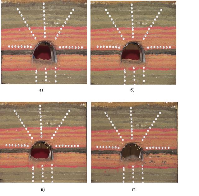
Figure 2. Status of development of the model number 3 at the time: (a) – of making and (b) – start the installation reinforcing roof bolting, and (c) – the installation reinforcing roof bolting, and (d) – the end of the mining model
As a result of processing the results were constructed graphs of the relative displacement of the deep frames in the top of the development and the coefficient of loosening of rocks on the distance to its contour, which are presented in Figure3.
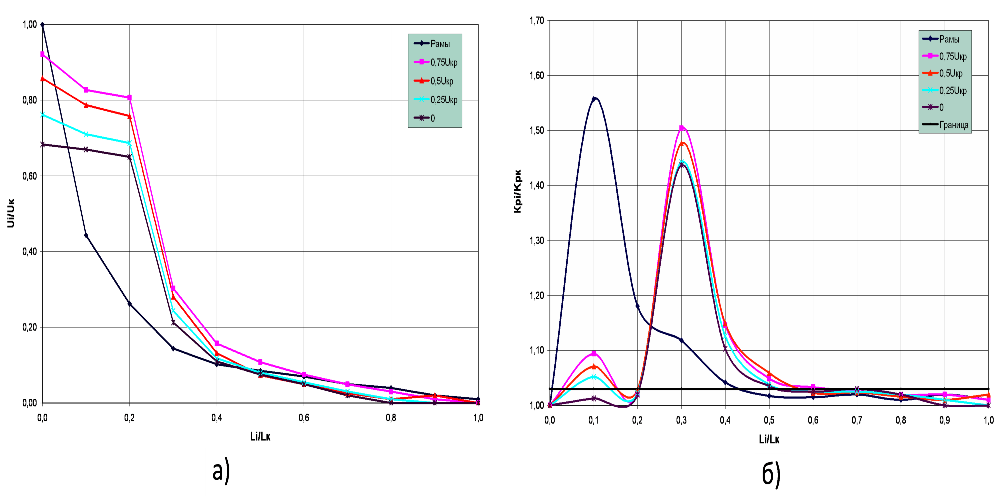
Figure 3. Plots of the relative displacements of the deep frames in the top of the development (at) (a) and the coefficient of loosening of rocks between the reference points (b) the distance from its contour at different values of the critical displacement carried out before the installation of anchors
Analyzing the graphs can be stated that the amplification frame lining anchors:
- No lag on the bottom for the formulation, implementation and after 25, 50 and 75 % of the final displacement contour displacement are reduced by 32, 26, 14 and 8 %.
- When the frame and roof bolting at the same time, and after the implementation of 25, 50 and 75 % of end offsets to reduce the final size of ZND in the first case by 30 % in the other there is a partial or complete destruction of rocks, reinforced with anchors. The maximum value of the coefficient of rock loosening moves deeper into the 0.2 size ZND.
- The outer limit of ZRP with realizatsii25, 50, and 75 % of the final displacement is at a distance of 0.5– 0.63 on the size of ZND.
Conclusions and directions for further research.
The research resulted in an opportunity to assess the impact of frame lining, reinforced with rigid anchors on the process of developing around the ZRP, which will be used to determine the rational parameters of the combined lining.
References
- Борисов А.А. Новые методы расчета штанговой крепи / А.А. Борисов. – М.: Госгортехиздат, 1962. – 125 с.
- Горбачев Т.Ф., Штумпф Г.Г., Стыгин Б.И. Применение анкерной крепи в подготовительных выработках – Т.Ф. Горбачев, Г.Г. Штумпф, Б.И. Стрыгин. – Новосибирск: Наука, 1972. – 246 с.
- Широков А.П., Лидер В.А., Писляов Б.Г. Расчет анкерной крепи ля различных условий применения/А.П. Широков, В.А. Лидер, Б.Г. Писляков. – М.: Недра, 1976. – 208 с
- Косков И.Г. Опыт применения анкерной крепи на шахтах Челяюбинского бассейна/ И.Г. Косков. М.: ЦНИЭИуголь, 1976. – 29 с.
- Мельников Н.И. Анкерная крепь/Н.И. Мельников. – М.: Недра, 1980. – 252 с.
- Булат А.Ф., В.В. Виноградов Опорно-анкерное крепление гонных выработок угольных шахт/А.Ф. Булат, В.В. Виноградов. – Днепропетровск: «Вильпо», 2002. v 371 с.
- Указания по рациональному расположению, охране и поддержанию горных выработок на угольных шахтах СССР. ВНИМИ, 1986 – 222 с.
- СОУ 10.1.05411357.010:2008. Система обеспечения надежного и безопасного функционирования горных выработок с анкерным креплением. Общие технические требования. – 89 с.
- Черев Д.А. Выбор параметров рамно-анкерной крепи на основе исследования закономерностей изменения внутренних усилий: Автореферат диссертации на соискание ученой степени кандидата технических наук по специальности 225.0022 – Геотехнология (открытая, подземная и строительная)/Д.А. Черев: Екатеринбург, 2004. – 18 с.
- Широков А.П. Теория и практика применения анкерной крепи/А.П. Широков – М.: Недра. 1981. – 381 с.
- Широков А.П., Горбунов В.Ф. Повышение устойчивости горных пород/А.П. Широков, В.Ф. Горбунов – Новосибирск: Наука, 1983. – 167 с.
- Правила безопасности в угольных и сланцевых шахтах. – М.: Недра, 1986. – 447 с. Югон А., Кост А. Штанговое крепление горных пород/А. Югон, А. Кост – М.: Госгортехиздат. 1962. – 238 с.
- Ткачев В.А. Установление рациональных параметров и области применения анкерной крепи в сочетании с рамными крепями в выемочных штреках: Дисс. канд.техн.наук/В.А. Ткачев - М., 1976. – 155 с.
- Указания по рациональному расположению, охране и поддержанию горных выработок на угольных шахтах СССР. – Изд. 4-е, дополненное. Л., 1986. – 222 с.
- Якоби О. Практика управления горным давлением./О. Якоби – М.: Недра, 1987. – 566 с.
- Руппенейт К.В. Некоторые вопросы механики горных пород./К.В. Руппенейт - М. : Углетехиздат, 1954. – 384 с.
- Литвинский Г.Г. Кинетика хрупкого разрушения породного массива в окрестности горной выработки./Г.Г. Литвинский – ФЕПРПИ, 1974. – № 5. – С. 15–22
- Евсеев В.С., Утрихин А.Н., Мурашев В.И. Определение предельной глубины применения анкерной крепи в подготовительных выработках //В.С. Евсеев, А.Н. Утрихин, В.И. Мурашев – Уголь. – 1984. – № 6. – С. 18-20.
- Махно Е.Я. К вопросу о расчете штанговой крепи /Е.Я. Махно – Уголь. – 1959. – № 5. – С. 41-42.
- Клюев А.П. Обоснование параметров крепления подготовительных выработок податливой анкерно - рамной крепью в зоне влияния очистных работ: Дисс. кан.тех.наук/А.П. Клюев. – Донецк. – 1989. – 213 с.
- Югон А., Кост А. Штанговое крепление горных пород/А. Югон, А. Кост – М.: Госгортехиздат. 1962. – 238 с.
- Заславский Ю.З., Мостков В.М. Крепление подземных сооружений/Ю.З. Заславский, В.М. Мостков – Недра, 1979. – 325 с