
Abstract
Content
- Introduction
- 1. The theme actuality
- 2. The aims and purposes of the work
- 3. The overview of world researches
- 4. The overview of Ukrainian researches
- 5. Content of the work
- 5.1 Expected displacements and deformations of the earth surface calculation techniques
- 5.2 The purpose and research techniques of the angular earth surface’s displacement process parameters while mining lava in the direction which is diagonal to the seam's strike direction
- 5.3 The prognosis of displacements and deformations of the earth surface while mining lava in the direction which is diagonal to the seam's strike direction in the Ansys
- Conclusion
- References
Introduction
Coal deposits underground mining causes displacements and deformation of the earth surface and the objects that are situated in the undermining zone. Therefore, coal excavation under the objects is based on the projects of their undermining. The main elements of these projects are the prognosis of surface subsidence and displacements caused by the mining activities, and assessment of their impact on the protected objects.
The existing displacement and deformations of the earth surface prognosis techniques, based on the method of typical single subsidence curves, prevail both in Ukraine and abroad and are extremely effective for projection.
These prognosis techniques are branch standards regulatory documents [ 1 , 2 , 3 ] and regulate the earth surface objects undermining. The techniques mentioned above are being constantly developed and improved in the leading scientific centers of mining science, in particular at the Institute of the Ukrainian Research Institute of NASU, Donetsk National Technical University, Novosibirsk State University, and others [ 4 ].
1. The theme actuality
Displacements and deformations in the main sections of the earth surface displacement trough are calculated in the process of coal deposits underground mining. The analysis of existing literature clears the fact that while the subject of the displacements and deformations process while mining lava along and across the strike is studied fairly well, the subject of the displacements and deformations process while mining lava in the direction that is diagonal to the strike remains not studied enough. Therefore, the research of angular earth surface’s displacement process parameters while mining lava in the direction which is diagonal to the seam's strike direction is a relevant scientific and technical task.
2. The aims and purposes of the work
The aim is to determine the angular earth surface’s displacement process parameters while mining lava in the direction which is diagonal to the seam's strike direction.
Research objectives:
– analysis of existing displacements and deformations of the earth surface prognosis techniques;
– development of graphical techniques in determining of angular earth surface’s displacement process parameters while mining lava in the direction which is diagonal to the seam's strike direction;
– suggestions about displacements and deformations of the earth surface prognosis techniques while mining lava in the direction which is diagonal to the seam's strike direction - graphically and analytically;
– prognosis of displacements and deformations of the earth surface while mining lava in the direction which is diagonal to the seam's strike direction using Ansys.
The idea of the work is to determine the angular earth surface’s displacement process parameters while mining lava in the direction which is diagonal to the seam's strike direction.
3. The overview of world researches
Studies on the subject of master's work in the world are taking places in Surveying Department of St. Petersburg State Mining University, the Institute of Mining Ural Branch of RAS, and a number of educational institutions in Poland
4. The overview of Ukrainian researches
Mine Surveying Department of Donetsk National Technical University and Dnipropetrovsk Mining University are studying displacements and deformations of the earth surface processes while mining lava in the direction which is diagonal to the seam's strike direction.
5. Content of the work
5.1 Expected displacements and deformations of the earth surface calculation techniques
The first part of the work is the analysis of researches and relevant displacements and deformations of the earth surface prognosis techniques.
The analysis of strata movement and structures protection is necessary to provide complete and efficient mineral extraction from the subsoil. Considerable amount of mineral resources is being under built-up area in the main mining regions of the country. Battery of studies has been done to devise effective safeguarding methods. Studies were conducted by instrumental observations in natural conditions on specifically laid stations and modeling on equivalent materials. In a number of basins observations have been going on for decades. With colligation and analysis of extensive data observations it is possible to elicit basic strata movement regularities and devise displacements and deformations of the earth surface techniques that have been widely used.
Currently used calculation techniques are suitable for situations when the location of excavation in the seam is either known (full procedure) or unknown (simplified procedure). In the first case expected and calculated deformations are determined, in the second case – probable deformations.
Simplified calculation procedure determines maximum earth surface deformations during the excavation of one seam as well as during strata series excavation. Existing calculation techniques are of limited use. They are not applicable in particularly difficult geological and mining conditions, such as disjunctive geological strata irregularities, bedding folded strata, mountainous terrain, mining reservoir chamber system, etc.
Full procedure determines expected deformation of the earth surface at any spot of the basin subsidence. Typical vertical displacement distribution curves are bases of this group of techniques. There are theoretical and empirical typical curves determination techniques. Empirical typical curves, based directly on field data and given in tabular form, graphically and by selection of approximating functions, are in the most use. Typical curves techniques are proved to be the most convenient method. Having field observations, it is easy to make typical curves for specific mining-geological conditions of the mine or district. Meanwhile displacements and deformations calculation formulas remain the same. Surface displacement is influenced by many factors, for example: mining operations depth, dip angle, seam thickness, excavation size, physical and mechanical rocks properties. Specifically processed graphs reveal common properties in the displacements and deformations distribution. These common properties are shown in typical graphs of vertical displacements (subsidence) and deformations.
Individual curves do not depend on the mining depth, dip angles or seam thickness. Therefore, transforming graphs into single curves allows combined processing of the observational data by setups and making average single curves, that are typical graphs of vertical displacements and deformations [ 5 ].
One aspect of improving the displacements and deformations prognosis techniques connected with the direction of lava excavation regarding the seam strike is studied in this work.
At the present time, current techniques recommend to calculate displacements and deformations of the earth surface along and across the strike. While determining excavation influence zone edges of influence it is allowed to smooth the difficult contour of the extracted area if the size of contour projections is not bigger than 0.2 N (where N is the occurrence depth of the seam in meters). Smoothing excavation contour is parallel to the development of the strike by the principle of excavation area conservation as shown in Figure 1.
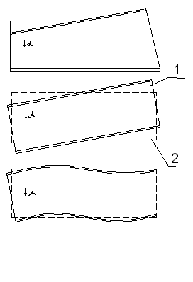
Figure 1 – Smoothing excavation contours of various configurations
1 – factual excavation contour; 2 – smoothed excavation contour
Expected displacements and deformations of the earth surface calculation techniques are based on the normative document "Regulations for undermining buildings, structures and natural objects during underground excavation of coal" [ 1 ].
5.2 The purpose and research techniques of the angular earth surface’s displacement process parameters while mining lava in the direction which is diagonal to the seam's strike direction
The calculation of the expected displacement and deformation of Earth's surface can be made anywhere in the displacement trough. There are two main sections of the displacement trough at the surface: along the strike and across the strike. Typically, monitoring of the earth surface displacement is based on main lines benchmarks which are located in the main sections or near main sections of trough, parallel to them. Observations on these main lines allow to determine displacement trough edges in the main sections [ 5 ].
At present, many mines extract lava in the direction that is diagonal to the strike direction, ie at the angle "є", as shown in Figure 2. According to [ 1 ] in relation to this excavation there should be smoothing of the contour parallel to the development of the strike by the principle of excavation area which means that displacement trough will be smoothed as well. However, it is advisable to do calculations above and across the seam’s strike of diagonal lava (the axes X ', Y') (Figure 2).
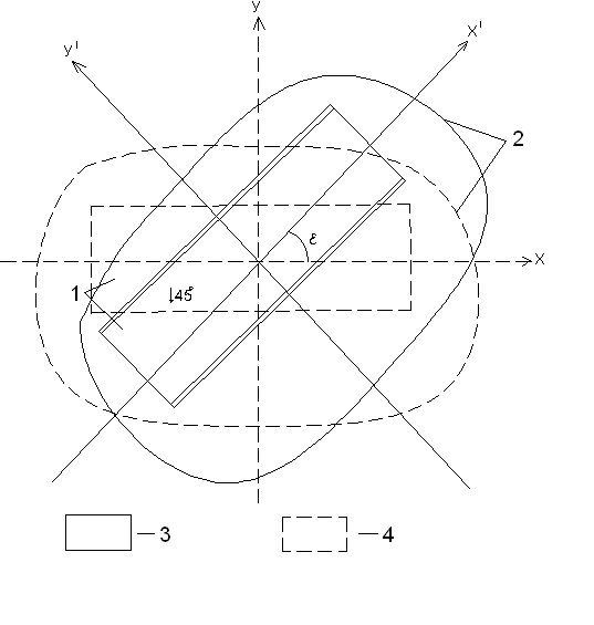
Figure 2 – Smoothing the diagonal lava
1 – lava; 2 – displacement trough; 3 – factual excavation contour; 4 – smoothed excavation contour for the calculation of projected displacements
Therefore, the work is to develop techniques of determining the angular displacements and deformations process parameters while changing calculations from above and across the strike to the diagonal direction.
The input parameters for the calculation of displacements and deformations are:
– boundary angles in degrees;
– angle of maximum subsidence in degrees;
– total displacement angles in degrees;
– the relative magnitude of the maximum subsidence;
– the relative magnitude of the maximum horizontal displacement.
In the first phase the study of single lava layer angular parameters with following information – seam thickness of 2.5 m, average mining operation depth of 800 m, dip angle of 45 degrees with the flat bottom of the trough formation – has been completed (Figure 3) [ 1 ].
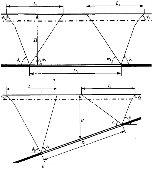
Figure 3 – Calculation of the displacement trough dimensions during full underworking of the earth surface
а – along the strike, б – across the strike
where H – average development depth, m;
D1, D2 – length of cleaning excavation, respectively, across and along the strike, m;
a – dip angle, degree;
h – thickness of overburden, m;
 – boundary angles, respectively, along the strike, by the rise and by the fall, degree;
 – boundary angle of overburden, degree;
 – total displacement angles, degrees.
From the center of the flat bottom lines are drawn through 30 degrees (Figure 4), lines are divided into spots after every 50 m, deformations in these spots are calculated using the program "ПОДРАБОТКА" (version 1.2).
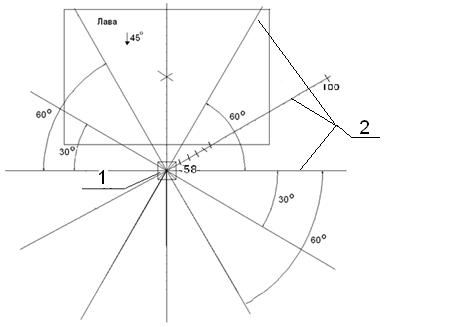
Figure 4 – The scheme of calculating the expected displacement and deformation of the earth surface
1 – flat bottom; 2 – lines of deformation calculating
After that, deformation graphs by each line are drawn to determine edges of the displacement trough (Figure 5).
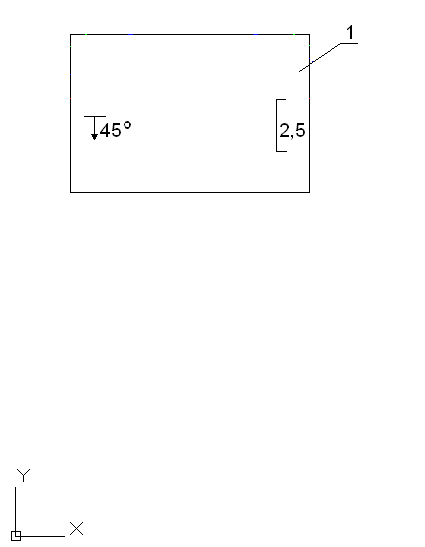
Figure 5 – Displacement trough
1 – lava; 2 – flat bottom; 3 – line of the subsidence calculation; 4 – boundary of the flat bottom; 5 – border of the trough by subsidence; 6 – border of the trough by curvature; 7 – border of the trough by horizontal deformations
(7 personnel, 7 cycles of repetition, 43.5 KB)
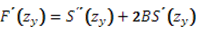
Analytical calculation of displacements and deformations anywhere in the displacement trough is made by following formulas as it shown in figure 6:
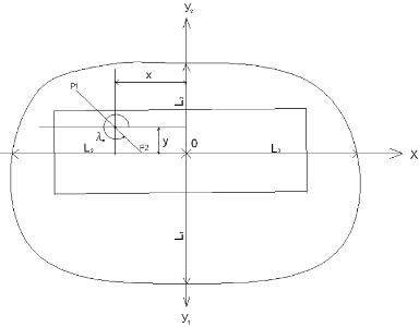
Figure 6 – Arrangement of the coordinate axes during deformation calculations
– calculation of subsidence
– calculation of slope
– determination of horizontal deformation

where 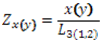
 – magnitude of the maximum subsidence
 – magnitude of the slopes along and across the strike, respectively:
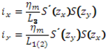
 – value of the horizontal deformation along and across the strike, respectively:
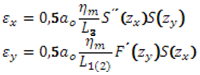
value of function is determined by the following formula:
 – relative magnitude of the maximum horizontal displacement;
 – dip angle, degree;
h and hм – thickness of overburden and mesozoic sediments, m;
Hа – average excavation depth, m;
S(zх), S(zу), S'(zх), S'(zу), S''(zх), S''(zу) – function of typical curves that characterize the pattern of displacements and deformations distribution in the half-trough. The values of S'(zх) take the negative in areas where x> 0, positive where x<0. The values of S'(zу) take the negative by the rise in the half-trough (y>0) and positive by the fall in the half-trough (у<0);
 – half-trough length by the fall, by the rise and along the strike the reservoir, respectively;
 – angle of conventional coordinate system turn [1].
5.3 The prognosis of displacements and deformations of the earth surface while mining lava in the direction which is diagonal to the seam's strike direction in the Ansys
The next part of the master's work is to determine displacements and deformations of the earth surface using Ansys (versatile software system for finite-element analysis).
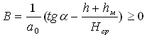
The sequence of rocks prior to mining is in conditions of natural stress state created by a mass of rocks. The pressure per unit area in a pristine massif is usually equated to the mass of the overlying column (Figure 7), that is

where  – weighted average rock density, kg/m3;
Н – depth of the design, m
Figure 7 – Diagrams of strain distribution around preliminary excavation
The lateral components of the vertical strain are  will be

where k<=1 – coefficient of lateral thrust.
After the excavation there is a redistribution of strain in a certain area in the value , per unit area is perekontsentratsiya stress in some region of the array adjacent to the development. At some distance from the excavation section strains values  take the initial value.
Strain increase around the side walls of the excavation (diagram 1) can cause crushing of the pillar edges of the rear sight and the displacement of rocks or minerals in the direction of excavation. The maximum strain is shifted by some distance toward the pillar (points A and B of diagrams 2) [ 6 ].
The strain condition in the spot is determined by a combination of normal and shear strains, drawn through this spot, that exist in the sections.
Determination of volumetric strain condition at any site (Figure 8) with known main strains is calculated by the following formulas:
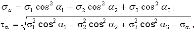
where  – angles between the normal and directions of the main strains.
Figure 8 – The strain condition of the massif
The highest shear strain: 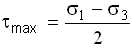 .
.
It appears on the ground parallel to the main strain  and inclined at an angle of 45 degrees to the main strains and
  .
.
Plane strain condition is a special case of the volumetric and can also be described by three circles of Mohr (Figure 9), one of the main strains must be equal to 0. For shear strains as well is true the law of pairing: the components of shear strains on mutually perpendicular grounds, that are perpendicular to the line of grounds intersection, are equal in magnitude and opposite in direction [ 7 ].
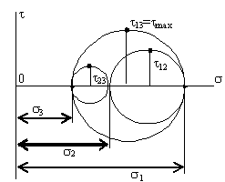
Figure 9 – Mohr circles
The shear strain can be shown as a linear function:
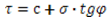
where с – cohesion, Pa;
 – normal strains, Pa;
 – abstract angle (the angle of internal friction).
Conclusion
The master’s work objective, which is suggestions of displacements and deformations of the earth surface prognosis techniques while mining lava in the direction which is diagonal to the seam's strike direction, is of current scientific and practical interest.
Further calculations and the analysis of suitable displacements and deformations of the earth surface estimation techniques are to be done in the future.
References
- Правила подработки зданий, сооружений и природных объектов при добыче угля подземным способом. Официальное издание – К.: 2004. – 128 с.
- Правила охраны сооружений и природных объектов от вредного влияния подземных горных разработок на угольных месторождениях: Утв. Госгортехнадзором РФ 16.06.98. – СПб., 1998. – 290 с.
- ГСТУ 101.00159226.001-2003. Правила підробки будівель, споруд і природних об’єктів при видобуванні вугілля підземним способом: Введ. 01.01.2004. – Київ, 2004. – 128 с.
- Грищенков Н.Н., Шнеер В.Р., Блинникова Е.В. Особенности мульды сдвижения и зон деформаций в ней при отработке наклонных угольных пластов. УДК 622.834(043)
- Борщ-Компониец В.И., Батугина И.М., Варлашкин В.М. Сдвижение горных пород и земной поверхности при подземных разработках. Под общей ред. проф., д-ра тех. наук Букринского В.А. и канд. техн. наук Орлова Г.В. М. Недра, 1984. 247 с.
- Оглоблин Д.Н., Герасименко Г.И., Акимов А.Г. Маркшейдерское дело: Учебник для вузов/ 3-е изд., перераб и доп. М., «Недра», 1981. 704 с.
- Расчет напряженного состояния. [Электронный ресурс]. – Режим доступа: http://sm.teormex.net.
Important Note
This work hasn’t been finished. The final results will be available in December 2012. The full text of the work and corresponding materials can be received from either the author or the supervisor after the date mentioned above.