
Abstract
Content
- Introduction
- 1. Relevance of the topic
- 2. The purpose and objectives of the study, research methods
- 3. The practical significance
- 4. Review of Research and Development
- Conclusion
- References
Introduction
With the widespread drilling and blasting method of mining we must pay enough attention to its improvement. As established by the survey a large number of excavations at many mines of the Donets Basin, with drilling and blasting method often incorrectly production are outlined, there are surpluses of large rocks, excessive destruction of the aquifer solid, high-quality backing unkindly - fixing space and cost overruns of concrete (for attaching a monolithic concrete).
Surpluses, sometimes exceeding 20-30% cross-sectional area of project developments, are the cause of the increased work of loading and transporting rock and laying fixing space, while the monolithic concrete lining - also cause large cost overruns of the concrete.
Wrong, not smooth contouring generation, not zabuchennye surpluses - a cavity in the fixing space worsen working conditions and reduce the stability of the lining of output.
As for the crack in the aquifer array, the following should be noted. It has been long known that when blasting shpurovyh charges in underground mines around the contouring blast holes are formed and the semicircular radial crack depth of 15-20 cm, but apart from them in the aquifer the array, as defined by the authors of the book, there are many cracks and fissures formations, parallel or nearly parallel the sides and top soil excavation. Depth distribution of up to 70-75 cm in the sandstones, in the slates 120-125 cm. These cracks and fissures suite, which was not previously known to significantly reduce the strength of the natural aquifer rock solid stability of the latest developments and lead to frequent repairs.
All the above indicates the need for more demanding for quality of work for the complex-mountainings workings, especially in the deeper horizons. Methods of excavation should be changed so that surplus breed were kept minimal and the maximum strength of the natural rock. These requirements are facilitated by gentle excavation method of contour blasting [2].
1. Relevance of the topic
By degree of loading of pairing barrels with horizontal workings (developments) in the yard near barrel there are selected 4 zones[1]: 1 Zone – adjoining of the barrel to the horizontal development, Zone 2 - also to the soil excavation, Zone 3 - the most weakness cross of pairing, 4 zone – the zone with the most weakness cross of the horizontal development.
Based on research carried out at the Ukrainian Research Institute, we can conclude that the parts of vertical barrels, that are in the zones of influence of workings near barrels, are the most difficult in terms of pairing crosscuts. More than 70% of violations in the sinking of boreholes in the Donetsk region accounts for the zone of pairings.
The main types of violations are the crack array, weirs, dumped rock. In this regard, reduced amounts of excess repel rocks and, therefore, the consumption of concrete required to consolidate the workings.
Thus there is a need to find ways to improve technology crosscuts pair of vertical shafts, the development of technological solutions to increase the rate of penetration of the trunk and reduce the cost of fixing.
2. The purpose and objectives of the study, research methods
The aim - to improve the stability of the interfaces and reduce the excessive destruction of the array.
The main objectives of the study:
- To analyze the structure of technology interfaces;
- Determine the factors influencing the parameters of construction technology interfaces with vertical shafts okolostvolnym yard;
- Develop a finite element model of the building interfaces;
- Develop technological regulations for the effective construction of conjugate vertical shafts.
Research object: aquifer array coupling shafts of coal mines.
Research subject: technology of BSB with contour blasting.
Methods: mathematical and static analysis of the results of experimental and laboratory research, an analytical method using a computer, the method of engineering analysis.
3. The practical significance
Improving the stability of interfaces and reducing the volume of permanent concrete lining.
Review of Research and Development
The using of contour blasting is primarily due to economic considerations. It reduces the amount of excess repel rocks and, therefore, the consumption of concrete required to consolidate the workings. The walls, formed by this method have a high resistance, so that there is no need for their maintenance.
According to [3], contour blasting has the following features: the destruction of the species with the required degree of fragmentation, displacement of the material in the desired location, without the expansion, aquifer preservation intact of the array, reducing the seismic impact of the explosion.
According to the classification of Shvanenberg, there are four main methods of contour blasting (Fig. 1) [5].
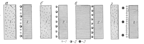
Figure 1 Classification of methods for contour blasting Shvanenbergu.
1 - guide hole, and 2 - charge with a reduced density (lightweight), and 3 normal charge density; I - array broken explosion ripping; II - aquifer intact array.
There are two technologies - depending on the presence (Fig. 1a) or absence (Fig. 1b) of the guide holes. According to this classification there are distinguished: the screened blasting cushion blasting (see Fig. 1a, b), borehole charges with a reduced density of the explosive with a large diameter tamping, used primarily for work on the surface; smooth blasting (Fig. 1b) - borehole charges with a reduced density of the explosive smaller diameter, without tamping, used mainly by sinking; pre-shearing, prc-splitting (Fig. 1,); line drilling (Fig. 1, d). In this case it is assumed that, in principle, the difference between the methods cushion blasting and smooth blasting does not exist.
In a well-known classification, published in [6] excluded methods without the use of explosives in a number of wells contour (line drilling), and for methods of using the blasting of the main criteria adopted by the sequence of processes of explosion. On the basis of different variants of contour blasting: before breaking the central part of the face and after it, and, moreover, in the direction of the contour relative to the plane of the wells (parallel or perpendicular).
Widely used method of contour blasting, followed by the delineation of explosives in the contouring of small-diameter boreholes charges of powerful explosive charges and small-diameter low-power explosives.

Animation – Drilling holes in the sinking of the method of contour blasting mate
To carry out Blast-contoured mine workings to perform the following activities:
- The implementation of high-precision values shown in the passports of blasting, to be sure marking boreholes and drilling angles strictly maintain the surface of the bottom holes to develop;
- a decrease in 2 ... 4 times against the conventional energy of the explosion in the contouring boreholes. The latter is achieved by using explosive cartridges with reduced diameter (in the case of the ammonites of T-19, PZHV-20, AP-5-LH - bullets diameter 27 ... 28 mm detonit M - 21 ... 22 mm) cartridges or using low-yield explosives (E-uglenit 6) 36 mm in diameter;
- using a special method of calculating the parameters of the charge and location of holes.
The initial data for a passport at the contour blasting, as suggested Shevtsov N.R., Taranov, you can use a valid passport for the conventional method of drilling and blasting operations for the production, as amended by the adjusted data for holes and row near contour. [7]
According to [8] the mass of the charge contour qш.к and near contour qш.пк series should be calculated by the formulas:
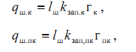
where kзап.к = 0,6…0,7 – filling factor of the contour of the hole rows;
kзап.пк = 0,4…0,6 – filling factor of the hole row near contour;
гк и гпк – Weight, kg, 1 m charge in contouring and boreholes near contour,
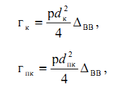
dк – diameter cartridges of explosives in the hole contour of the series (made in the application of ammonites 27 ... 28 mm detonit M - 21 ... 22 mm);
dпк – diameter cartridges of explosives in boreholes row near contour (36 mm or 32 mm).
The calculated mass of the charge holes of contour and row near contour rounded to a specified number of rounds in the hole. The depth of holes in the transition to contour blasting is equal to the depth adopted in the elaboration of the usual blasting.
The distances between the contour and the ак near contour апк hole (Fig. 12.1), and LNS, for these holes, and Wк, Wпк should be calculated by the formulas:
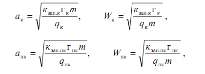
where m – the coefficient of convergence of the charges in the layered rocks in the excavations carried out along strike (m = 0,8 at the walls of the development and m = 1, ... 1.2 in the roof);
qк и qпк – specific consumption of explosives in kg / m contour for the zone and the holes near contour
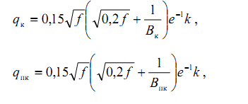
where Вк и Впк – long lines, which are contouring and boreholes near contour.

Figure 2 – Scheme to determine the distance between the contouring and ак predkonturnymi апк шпурами [9]
Conclusion
By analyzing the concept of contour blasting, I came to the conclusion that the main purpose is to protect its aquifer from violations of the array, and that traces of wells depends on the disturbance of the array. The use of contour blasting virtually eliminated the processes of crack formation in the aquifer array, whose stability has increased dramatically. Contour blasting is recommended for carrying out all types of mining: horizontal, inclined or vertical, and the formation of field, capital and training.
References
- A. Borodulya AA Obґruntuvannya parametrіv concrete anchor-hour krіplennya pid sporudzhennya spoluchen vertical stvolіv vugіlnih Mines: Abstract. thesis. Candidate. Technical. Sciences: 05.15.04 / Nat. gіrn. Univ. - Dnіpropetrovsk, 2002. - 18.
- Taranov P. Contour and others blasting in coal mines. Donetsk, "Donbass", 1972.
- Brotanek I., J. Water Contour blasting in mining and construction. Moscow, Nedra, 1983, 144 p.
- L.I. Baron, Turchaninov IA Klyuchnikov A. Violations of the rocks in contour blasting. L., Science, 1975.
- Din 20163. Sprengtechnik. Begriffe, Einheilen, Formelzeichen, Mai 1973.
- LI Baron, A. Klyuchnikov Contour blasting for drifting mines. L., Science, 1967.
- Shevtsov, NR, P. Taranov, Levit V., Hutz AG Destruction of rocks by explosion: A Textbook for high schools. - 4th edition revised and enlarged - Donetsk, 2003. - 253 p.
- Methodical instructions to calculated parameters and the preparation of passports BSB during construction of underground mining (for students majoring in 7.090303,7.090301.02, 7.090301.05, 7.090301.06, 7.070801.06) / Comp.: NR Shevtsov, S. Borschevsky, VF Formosa, KN Labinsky. - Donetsk: 2000 - 31 p.
- Manufacturing model generation curved - form ustupnoy heading slaughter. Ph.D., Assoc. Shkumatov AN, stud. IA Cherkasov, stud. Hvostovsky K. Improved technology in the construction of shafts and underground facilities. Sat Nauchn. works. No. 15. - Donetsk:
Nord-Press
, 2009.