
Summary of final work on the topic
Contents
- Introduction
- 1. Relevance of the topic
- 2. The purpose and objectives of the study, expected results
- 3. Review of Research and Development
- 3.1 Overview of international sources
- 3.2 Overview of national sources
- 3.3 Review of local sources
- 4. The first section
- 5. The use of Ansys
- Conclusions
- Source List
Introduction
Surveying services monitor the safe conduct of mining operations.
In the development of the mines there are danger zones, where the development is impossible without taking additional security measures. Currently, the development of mineral resource recovery is impossible without the use of barrier pillars.
Barrier pillar – part of the mineral deposits left by the mines to protect against possible breaches of water from the aquifer and the closely spaced water bodies (rivers, lakes, ponds, etc.), [ 1 ] as well as the inrush of water, gas or zailovochnoy clay from the previously passed and flooded workings of adjacent mines rear sight also serves as a barrier to separate the mine fields of the neighboring businesses. In the intact rock mass are in a stressed state, and after carrying out mining in and around the oral cavity after the coal is concentrated zone of bearing pressure. As we have already established zones of high pressure formed over and under the full and marginal parts of the lava, and intact coal pillars stand in a stress concentrator ugleporodnom array. At present, the study of the stress state of the bottom hole of the coal seam is assumed that it is in the zone of influence of output. Schematically, such a division into zones of influence and the development of pristine
array is shown in Figure 1. [ 2 ].

Figure 1 - Schematic cross section of the working face of rectangular shape, the IM Petukhov [ 2 ]
1 – area of influence of production, 2 – zone of bearing pressure, and 3 – the border zone of discharge, 4 – boundary protected area; 5 – boundary zone complete displacement, 6 – zone displacement of rocks and the earth's surface resulting from the deformation of the array in the area bearing pressure
1. Relevance of the topic
Therefore, the actual scientific and practical task is to study the stress–strain state of the coal seam and surrounding rock mass in the vicinity of the barrier pillars at different powerful fortress of rocks and soils of the roof of the coal seam, the study of geomechanical processes in rock mass at delineating mezhdushahtnogo barrier rear sight in order to optimize the size of sewage generation in the planning of mining operations at different depths of their conduct, the degree of destruction issledovaninie mezhdushahtnyh barrier pillars and prevent the penetration of water into the existing mine workings of the mine, in the event of flooding of the mine workings nearby.

Figure 2 – the destruction of the pillar as mining Formation reservoir
2. The purpose and objectives of the study, expected outcomes
idea work is to use the relationship between mechanical properties and the geological and technological parameters and the size of the rear sight.
The purpose of the work to improve mine safety by determining the design parameters of the barrier pillar.
To achieve this goal, the following research objectives:
- To study the problem of ensuring the stability of the barrier pillars, to analyze the methodology of calculation of barrier pillars and their security measures;
- Statement of the problem, identification and justification of the limiting conditions and procedures for the job;
- Justification of the method of finite elements and the factors studied as a basic research tool;
- Performing a numerical experiment
- analysis of the results
- Conclusions on the results obtained
object of study : the process of stress redistribution of the barrier pillar.
subject of study : parameters of the barrier pillars.
Expected results:
- design techniques of mathematical modeling of deformation and fracture at different depths mezhdushahtnyh barrier pillars in the suite of various layers of power under the influence of sewage treatment works in ugleporodnom array of different strength of rocks by finite element method;
- In developing the algorithm of formation of the nodal points and the software that implements the mathematical model of the processes occurring geomehanicheeskih;
- in preparation of design models and implementation of computational experiments;
- In the analysis and synthesis of the results.
3. Review of Research and Development
Because the extraction of minerals from the bowels of the land is developed around the world, its problems are engaged in all countries, including Ukraine.
3.1 Overview of international sources
At the present time to solve the problem of stability of barrier pillars in the international practice of using finite element methods [ 3 - 12 ].
3.2 Overview of research on the topic in Ukraine
In Ukraine, studies of geomechanical processes taking place in the array ugleporodnom by conducting underground mining activities, are engaged in scientific research institute of the Ukrainian Research Institute and the National Academy of Sciences Department of Physical and Technical Problems DonIPhT NAS. [ 13 ].
3.3 Overview of research on the topic in the Donetsk National Technical University
Department of Surveying at the Donetsk National Technical University is one of the leading scientific organizations, which deals with geomechanical processes in ugleporodnom array by conducting underground mining. These problems do Ph.D. . Professor. And Prof. NN Grishchenkov . Prof. VV Nazimko.
4. The first section
The first section of my master's work is devoted to reviewing existing literature for an analytical review of studies on the stress-strain state in the wastewater treatment works in the coal seams, the calculations of barrier pillars in the suite of layers is set as follows:
- In payment methods for determining the barrier pillars are not fully taken into account features of the flow of geomechanical processes in contouring pillar lavas, which depends primarily on the parameters of working faces, and the depth of the layer.
- Because prolonged exposure to areas of high rock pressure on the barrier pillar, part of its boundary is subjected to destruction. It is not fully accounted for in the existing formulas for the calculation of the barrier pillars.
- As a result moddelirovaniya we need to get information on the geomechanical processes not only at the borders and rock pillar, but also within the thickness of the roof and soil, as well as in the coal seam and the Formation reservoirs, preference was given to the method of finite elements.
5. The use of Ansys
ANSYS – versatile software system for finite element analysis, the existing and evolving over the past 30 years, is quite popular among professionals in the field of computer engineering and finite element solutions of linear and nonlinear, steady and unsteady three–dimensional problems of solid mechanics and mechanics of structures (including unsteady geometrically and physically nonlinear problems of contact interaction of structural elements), problems in the mechanics of fluids, heat transfer and heat transfer, electrodynamics, acoustics, mechanics and related fields. Modeling and analysis in some areas of the industry to avoid costly and lengthy development cycles, such as design – construction – testing.
The system operates on the basis of the geometric kernel Parasolid.
[ 14 ].
Strength analysis of structures is probably the most widespread application of finite element method. The term design refers not only to engineering structures such as bridges and buildings, but also to a variety of machine parts. The main unknowns to be determined in all types of strength analysis of structures are moving. The remaining quantities - strain, stress, effort – these are calculated from nodal displacements [ 15 - 16 ].
The program ANSYS provides the following types of strength analysis:
- static analysis – calculation of displacements, stresses, etc. under static loading;
- modal analysis – determination of natural frequencies and mode shapes;
- harmonic analysis – determination of the response to the construction of harmonic components of the disturbing load;
- dynamic analysis – determination of the design response to the action of arbitrary loads as a function of time;
- spectral analysis – extension of modal analysis to calculate the stresses and strains under the influence of the frequency spectrum or random vibration;
- stability analysis – calculation of critical loads and the determination of buckling.
In addition, it is possible to make special types of calculations in the field of fracture mechanics, strength of composite materials and fatigue.
Most of the ANSYS–elements are designed to perform calculations on the strength of structures – from simple beams and rods to the multilayer shells and solid bodies at high strains.
Database
The program ANSYS is used alone, the center, a database for the entire set of data pertaining to the model and the results of the solution (Fig. 3). Model information (including data on geometry of solid-state and finite–element models, material properties, etc.) written to the database on the preprocessor stage of preparation. Load and the results are written decision processor solutions. Data obtained on the basis of the decision at their Postprocessing, written postprocessor. The information entered by one of the processors are available, as appropriate, to other processors. For example, the general post–processor can read the data related to the solution and the model and then use them for computing postprotsessornyh [ 16 ].
File Format
Files are used to transmit data from one part of the program to another to create a database to store and output the results. These files include the database files, results, graphics, etc. Created by the program files are formatted ASCII (ie can be easily read and edited), or binary format. By default, binary files are created by ANSYS using an external format (IEEE Standard), which provides a variety of data processing hardware. For example, data on the geometry of the model can be created by the user in one computer system and then easily used by another user of the program is installed on a different platform [ 17 ].

Figure 3 - Chart links a central database program ANSYS
The emergence of computers has stimulated the development of finite element method (FEM), the mathematical foundations of which were formulated by the famous mathematician Courant in 1943, consider the application of this method to the calculation of the elastic plate, located under the plane stress condition, using the simplest triangular finite elements.
In Fig. 4 is a flat area made up of triangles. Each triangle is the final element that has its own serial number. Common vertices of triangular finite elements are called nodes, which are also numbered. The border region is a broken line. The kinematic boundary conditions are given at the nodes on the boundary. Pressures on the boundary are replaced by concentrated forces at the nodes, the connection between the finite elements are implemented in the nodes [ 18 ].
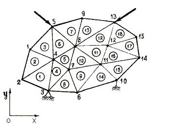
Figure 4 – The area consisting of triangles
At each node, the unknowns are moving along the axes Ox and Oy, denote the displacement at the node with number i in ui and yI (to the axes Ox and Oy, respectively). Let n – number of nodes in the selected partition. Then the total number of unknowns is equal to 2n.
Conclusions
Analytical methods for calculating the stress–strain state of rock mass in the vicinity of sewage and coal pillar workings allow with sufficient accuracy to determine the parameters of rock pressure in the vicinity of development workings, and treatment with the condition of the adjustments of physical and mechanical properties of rocks.
To justify the method of calculating the optimum dimensions of mining in the treatment of their layout near mezhdushahtnyh barrier pillars in the Saite layers, taking into account the depth of their strength and power of different rocks and soils of the roof of the coal seam is necessary to analyze and study the VAT system entirely – excavation – thickness of the host rocks. Mathematical methods for modeling geomechanical processes allow to analyze the effect of various technological schemes of mining seam near the rear sight.
Using computer modeling allows to conduct experiments on the destruction of the barrier pillars with less expenditure of time and money, rather than large–scale simulations in the laboratory. Application of the finite element method allows the computer simulation with high accuracy.
Complex finite–element method ANSYS is the best tool for the task, namely to study the stress-strain state of the pillars in the retinue of layers depending on the size of its contouring treatment workings, depth and power of the coal seam.
In writing this essay master's work is not yet complete. Date of completion: December 2012.
References
- Большая Советская Энциклопедия. М., т. 24, ч. I: Советская Энциклопедия, 1976, с. 62.
- Земисев В.Н. Расчеты деформаций горного массива. - М: Недра, 1973. –144 с.
- Atkinson R.H., Ko H.-Y. Statistical variation on the compliance of coal.- Proc.2nd Int.Conf.numerical Methods in Geo-mech., Blacksburg,Va.,USA,vol.1, 1976, pp.367-3SO.
- Blake W. Rock burst research at the Galena Mine»Wallace, Idaho. -US Bureau of Mines Techn.Progress Report 39».-Denver,Colorado,Aug.1971.
- Clough R.W. The finite element method in plane stress analysis. -Proc.2nd ASCE Conf.Electronic Computation, Pittsburg,Pa.,Sept.1960.
- Fadeev A.B., Abdyldaev E.K. Elastoplastic analysis of stresses in coal pillars by finite element method. Rock Mech., 1979, 11, pp.243-251.
- Gudehus G. Some interactions of finite element methods and Geomechanics: A survey.Ch.1. In: Finite elements in Geo-mechanics. Ed.by G.Gudehus. Chichester,John Wiley & Sons,1977,1979, pp.1-32.
- Heuze F.E., Yufin S.A. Finite element modelling of sequential excavation and rock reinforcement. Proc.lOth AIME Annual Meeting,Denver,Colorado»March 1978.
- Jenkins W.M. Matrix and digital computer methods in structural analysis. London.McGraw-Hill, 1969.
- Turner M.J.,Clough R.W., Martin H.C.,Topp L.J. Stiffness and deflection analysis of complex structures. J.Aeronaut. Sci.,1956, vol.23, U 9, pp.805-823.
- Whiteman J.R. A bibliography for finite elements. N.Y., Academic Press, 1975
- Zienkiewicz O.C. The finite element method. 3rd edition, London,McGraw-Hill B.Co.(US)Ltd.1977
- Правила подработки подземных сооружений и природных объектов при добыче угля полдземным способом. Минтопэнерго Украины. Киев. 2004.
- http://ru.wikipedia.org/wiki/ANSYS
- http://www.ansys.com/
- Басов К.А. ANSYS: справочник пользователя .- М.: ДМК Пресс, 2005. – 640с., ил.
- Басов К.А. Графический интерфейс комплекса Ansys - М.:ДМК Пресс, 2006.-248с.
- Басов К.А. Ansys в примерах и задачах - М.:Компьютер Пресс, 2002.-228с.