
Abstract
Content
- Introduction
- 1. Theme urgency
- 2. Goal and tasks of the research
- 3. Analytical review of the designs of submersible pumps
- 3.1 Analytical review of the existing designs of submersible pumps with hydraulically rodless spool fluid distribution.
- 3.2 Analytical review of the existing designs of submersible pumps with hydraulically besshtangovyh valve control.
- Conclusion
- References
Introduction
In connection with the reduction of surface water resources, the use of groundwater for various purposes is increasing significantly, so the creation of high-pressure and high-performance equipment for pumping liquid from the wells is of great economic importance. The need for such technology for dewatering mines mining industry is experiencing.
The analysis shows that one of the most interesting and promising liquid elevators are gidroporshnevye submersible pumps with hydro power from the valve control fluid.
When the improved design of hydraulic submersible pump for pumping fluid zashlamlennoy, as is often the hydraulic valve stuck, clogging sludge. You have to remove the pump to the surface and analyze.
In carrying out scientific work chosen method of calculating the operating parameters of the improved pump. Selected design and operational parameters are calculated pump.
The calculations confirm the hydraulic diameter of 89mm serviceability design pump unit for pumping fluid zashlamlennoy from a depth of 1000 m using conventional ground drive pumps are of PD included with the drilling rig to drill into solid minerals.
The technology of conducting pumping liquid submerged hydraulic pump.
1. Theme urgency
In connection with the reduction of surface water resources, the use of groundwater for various purposes is increasing significantly. Therefore, the creation of high-pressure and high-performance equipment for pumping liquid from the wells is of great economic importance. The need for such technology for dewatering mines mining industry is experiencing.
At the present time in our country and abroad use many different hardware for artificial lift fluid designed for different operating conditions, which differ structurally and on the principle of action. Their analysis shows that one of the most interesting and promising liquid elevators are submersible hydraulic submersible pumps.
Submersible pump with hydraulic drive mechanism is a bulk-type, a feature which is that one and the same amount of liquid with the same depth can be pumped at different costs and pressures of the working fluid, respectively. Conversely, when the pump power tributed parameters can be pumped out different amounts of fluid at different depths. This is achieved by selecting the ratio of area of ??the piston pump and motor.
Hydraulic submersible pumps differ from each other by:
– type hydraulic power cylinder and pump parts;
– the type of distribution mechanism of the engine;
– load distribution during the course of the pistons up and down;
– method of delivery into the hole and remove exhaust fluid from the well, etc.
When pumping liquids heavily sanded-in known gidroporshnevymi pump units with a hydraulic valve is a valve jamming of sludge, which often causes the pump to extract the surface for disassembly and cleaning.
In this context, improving the design of hydraulic submersible pump for pumping fluid from cuttings boreholes with a diameter more than 59mm depth of 1000m, is an actual scientific problem.
2. Goal and tasks of the research
The purpose of the work – to improve the design of hydraulic submersible pump for pumping liquid from the very cuttings boreholes with a diameter more than 59mm depth of 1000m.
To achieve this goal following tasks:
- Analysis of existing designs of submersible pumps with hydraulic engines with valve and slide the power distribution of the liquid.
- Improvement of methods for calculating the submersible pump to a hydraulic valve and the determination of its operating parameters.
- Improving the design of submersible pump with a hydraulic valve.
- Development of technology for the use of advanced design pump with a hydraulic motor to the valve during pumping of fluid from the well.
Methods of research: tasks are solved by compiling and analyzing patent and literature, theoretical research, implementation research and design work.
The scientific novelty: Refined method of calculation of the submersible pump with a hydraulic valve that allows you to study the patterns of advanced devices with a choice of an effective combination of design and size of the mechanism of hydraulic parameters: hydraulic pump-well.
The scientific value of the work: is the ability to use the resulting theoretical model and application of knowledge obtained in the drilling industry.
The practical value of the work: expressed in the creation of an effective pump design with a hydraulic valve by removing the possibility of jamming of hydraulic valves, the particles of the solid phase during pumping cuttings very fluid.
3. Analytical review of the designs of submersible pumps
3.1 Analytical review of the existing designs of submersible pumps with hydraulically rodless spool fluid distribution
Known hydraulic pump, the Department developed technology intelligence minerals deposit Yekaterinburg Institute of Mining, which has an engine with slide valve-fluid distribution (pic. 1)[1].
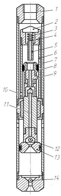
Рicture 1 – Submersible pump with a piston valve-spool hydraulic motor.
1 - head of the upper; 2 - Cover; 3 - Spring; 4 - the case limiter; 5 - stop moving; 6 - hydraulic cylinder;
7- casing; 8 - hydraulic piston; 9 - valve; 10 - window; 11 - channel in the rod; 12 - the discharge valve;
13 - piston pump; 14 - valve receiving.
The working fluid pumped from the surface of the pump power for water-pressure pipes, has access to the bottom of the cylinder 6 through the annular space between the casing 7 and the cylinder through the window 10.
If this valve 9 is in the up position, the piston 8 is due to the pressure of working fluid on its lower surface starts to move upwards, since the upper chamber of the cylinder 6 in this case is connected to the well through the window and the exhaust channel 11 in stock.
When the piston reaches the top position, the spool 9 to its end face rested in the limiter 5, move it up and compress the spring 3. With a further rise of the piston valve will shift to the neutral position, characterized by the simultaneous overlap of the exhaust windows[2].
Due to this pressure at the top of the cylinder 6 will increase dramatically. Due to the combined action of fluid pressure on the spool from the top of the cylinder 6 and the spring 3, he will be dead center position, open and close the inlet window exhaust window. The working fluid will have access to the upper chamber of the cylinder 6, and further moves the spool 9 in the lowest position. At the same time inlet window is fully open and exhaust closed[3].
Under the pressure of hydraulic fluid to the upper cavity of the piston 8 movable parts the whole system will move down.
In the lower position of the piston valve protrusion nine stops against the stop. Spool and stop further movement of the piston is moved to the neutral position, and then by the pressure of the liquid from the bottom of the cylinder will pass him and take up position. The upper chamber of the cylinder 6 connects to the atmosphere.
Begin the next stroke of nine upwards. In this case the exhaust fluid from the top of the cylinder will be forced out through the window and the exhaust channel 11 into the upper chamber above the piston pump 13 where it mixes with the liquid pumped from the well.
Thus, the hydraulic piston 9 and the associated pump piston 13 will perform a reciprocating motion.
When the piston 13 upward will suction the fluid out of the hole in the bottom of the cylinder through a valve 14 and the injection of working and mixed pumped liquid from the top of the cylinder of the pump in water lifting pipe. When the piston 13 down it will displace fluid from the bottom of the cylinder pump through valve 12 and the upper cavity and partly (in the volume of stem) in the lift pipe[4].
Submersible pump with known G. I. Neudachin end V. I. Pilipec (pic. 2), which has a valve-slide and the distribution of fluid sealing system seals and pistons capable of working in cuttings abrasive medium.
Valve spool fluid distribution site is located in the top of the cylinder of the hydraulic piston 5 and the switch 4 in its extreme positions.
The design feature is the presence of a special device which allows a stop in the event of an hydraulic valve in the intermediate position to rearrange them in the end position, without lifting a submersible unit on the surface.
Pump, cylinder with a diameter of 150 mm is 15 m3 / h, pressure up to 800 m.
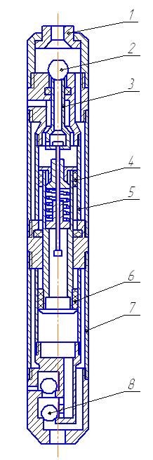
Рicture 2 – Hydraulic pump with valve-spool fluid distribution.
1 - device rearrangement emergency valves; 2 - hydraulic intake valve; 3 - valve; 4 - hydraulic piston;
5 - hydraulic cylinder; 6 - piston pump; 7 - pump cylinder; 8,9 - suction and discharge valve pump; 10 - rod.
The disadvantage of spool and valve-spool mechanism is the possibility of pumping in the main lubricating fluids such as oil. When evacuating cuttings water, which has an abrasive effect of the service life of hydraulic submersible little.
3.2 Analytical review of the existing designs of submersible pumps with hydraulically besshtangovyh valve control
Known reversing cylinder G. I. Neudachin to drive the submersible pump piston differential action (рiс. 3) consists of two valves, valve seats are made in the cylinder head fitted with holes for fluid, push rod, which interacts with the control valves. Switching valve is a piston.
Design flaw is the lack of protection from the exhaust valve of the fluid velocity head and the ability to work only in a strictly vertical wells, as the exhaust valve has no centering in the radial direction and moves with the piston.
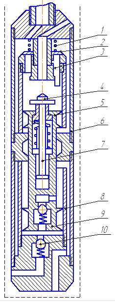
Рicture 3 – Reversible hydraulic cylinder.
1 - Spring; 2 - inlet valve; 3 - pushrod; 4 - valve outlet; 5 - hydraulic piston; 6 - hydraulic cylinder;
7 - draft; 8 - suction valve; 9 - piston pump; 10 - valve discharge.
Known gidroporshnevaya pump installation G. I. Neudachin and V. I. Pilipts (рiс. 4). It has a valve control hydraulic fluid and pump dual action.
When submitting a working fluid in the borehole hydraulic piston pump unit, it will fill the body and into the lower cavity of the engine cylinder, causing the rise of tightly interconnected hollow piston rod and thus the hydraulic pump with a balancing shaft[5].
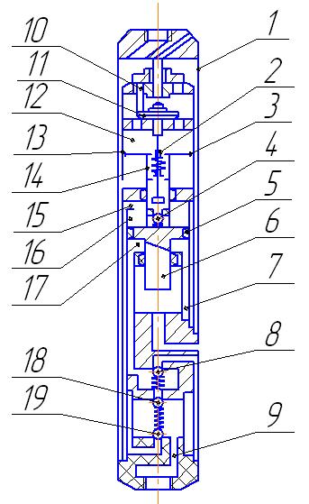
Рicture 4 – The hydraulic piston pump installation.
1 - housing; 2 - limiting; 3 - piston engine; 4 - valve; 5 - piston pump; 6 - a balancing rod; 7 - pump; 8 - valve;
9 - the discharge canal; 10 - pusher; 11 - final valve; 12 - hydraulic; 13 - cylinder; 14 - rod; 15 - window;
16 - channel above the cavity; 17 - under the piston cavity; 18 - the upper valve; 19 - foot valve.
The use of such devices can increase the pressure in the discharge channel of the pump that allows you to create an intensive washing to bursting slurry plugs. Hydraulic motor can be operated in an environment with a small amount of solid phase.
4.Justification of the choice of direction and design of the submersible pump is hydraulically rodless
The analysis found that the well-known hydraulic spool with the distribution can only work in the lubricating medium, and a valve control device of working fluid can work only in a slightly cattings fluid. However, the jamming of at least one of the valves have to remove the entire unit is submersible to the surface for disassembly and cleaning of the hydraulic valve.
Therefore, an improved hydraulic motor (рiс. 5), capable of operating in a highly fluid cuttings.
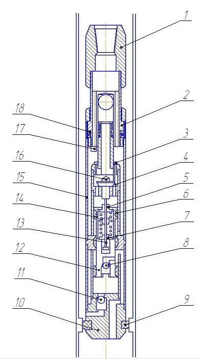
Рicture 5 – Submersible hydraulic pump.
1 - upper adapter; 2 - movable adapter; 3 - inlet valve; 4 - pusher; 5 - excess flow valve; 6 - hydraulic piston; 7 - excess flow valve; 8 - inlet valve; 9 - the cuff; 10 - Shank; 11 - suction valve;
12 - piston pump; 13 - traction; 14 - rod; 15 - hydraulic cylinder; 16 - the exhaust valve; 17 - ledge; 18 - seal.
In this design the hydraulic working fluid is distributed between the two valves, having the ability to self-packing as wear of working surfaces. In addition to the unit, a system of soft rubber seals for seals and pistons capable of operating in an abrasive environment. Therefore, as the working fluid can be applied pumped liquid, water or clay mud[6].
The upper is made of hydraulic motor advanced movable and in the case of the intake valve sticking cuttings down upper adapter, it falls into the protrusion groove valves and valve rotation down to his seat. Hydraulic motor back into operation[7].
In pic. 6 the scheme of a submersible pump installed in well.
")
Рicture 6 – Scheme of installation of submersible pump in the well.
Conclusion
The analysis of existing designs water-lifting equipment for selected research submersible piston pump, hydraulic motor having bivalve distribution of the working fluid.
In order to eliminate jamming of hydraulic valves, the particles of the solid phase during pumping cuttings much fluid in the proposed design of the valve made ??two grooves. The upper adapter is made movable, and it has two ledges.If jamming a slurry valves, turn off ground pump is lowered pipe string is given rotation, projections fall into the groove valve and sludge is ground and the valve is lowered into the saddle.
Thus, the developed design has a significant advantage – the upper coupler is made movable and jamming of valves can be removed without removing the unit to the surface.
In carrying out scientific work chosen method of calculating the operating parameters of the improved pump.
Selected design and operational parameters are calculated pump.
The technology of conducting pumping liquid submerged hydraulic pump.
The calculations confirm the hydraulic diameter of 89mm serviceability design pump unit for pumping fluid cuttings from a depth of 1000 m using conventional ground drive pumps are of PD included with the drilling rig to drill into solid minerals.
References
- Пилипец.В.И. Насосы для подъема жидкости. – Донецк: РИА, 2000. – 244 с.
- Богданов Н.А. Погружные центробежные насосы для добычи нефти. – М.Недра, 1968
- Неудачин. Г. И., Пилипец. В. И. Разработка гидрокачалки для привода штанговых насосов – М.: ЦНИИЭИУголь, №12, 1976.
- Неудачин. Г. И.., Пилипец. В. И Погружной пневматический насос.– М.: ЦНИИЭИУголь, №27, 1976
- Пилипец В.И. Применение погружных насосов с гидроприводом для откачки жидкости из буровых скважин. – Свердловск: СПИ. В кн.: Совершенствование техники и технологии бурения скважин на твердые полезные ископаемые. 1981.
- Анурьев В.И. Справочник конструктора-машиностроителя. – М.: Недра, 1978.
- Неудачин Г.И., Коломоец А. В., Калиниченко О. И., Пилипец В. И. Проектирование и расчет забойных буровых механизмов и погружных насосов. Учебное пособие. – Донецк: ДМТ, 1977.