
Abstract
Contents
- Introduction
- The main objectives of this work
- 1. The main characteristics of the ATS
- 2. The algorithm works ABP
- 2.1 Two inputs for a total bus system (primary and backup)
- 2.2 Two workers entering the partitioning c
- 2.3 Two working partitioning the input c + input from the EDL
- 3. relay monitors its own supply Un
- 4. Communication protocol Modbus slave
- 5. 5. Conclusion
- 6. References
Introduction
An important requirement in the power supply system is to ensure continuity of supply for power consumers. For these purposes, among other measures serve an automatic transfer switch (ATS).
The present work proposes a scheme ABP performed on the equipment Schneider Electric c using a smart relay Zelio Logic. It is based on a set of used, unified design solutions required for optimal (simplified) the development of NKU. A set of teaching materials and tools with a licensed expanding library of standard solutions to create a single database schema ABP, which can be used for the design of electrical installations in Ukraine. All the schemes of the control unit checked on a specialized stand, and finished HMI solutions commissioning Prisma Plus switchboards have been type tested in accordance to GOST R 51321.1 - 2000 (IEC 60439 1). The agreed work products increases the efficiency of the whole: enables discrimination protections electrodynamic resistance machines, boards, power distribution, as well as their thermal conditions. The main feature of the work is that the solutions provided by the ATS can be applied: -In function boards with modular construction «Prisma Plus», allowing create a customized electrical installation on the single line diagram, with fitted Typical panel changeover system, the appearance and dimensions of which are already presented in this paper; -In boards with a block design. At the same overall dimensions of panels presented by the manufacturer; -In switchboards for their own use and power KTP industrial use. Versatility solutions ATS makes them easy to adapt to the previously widely used electrical installations. Thanks to the proposed decisions ABP is possible to create a reliable, multifunctional meeting all standards, as well as optimal in cost of the circuit transfer switch. System selection and application standard solutions can provide convenient relationships between customers, design institutes and factories of manufacturers in order to pass NKU.
The main objectives of this work are:
-Creation of standard solutions of panels transfer switch that satisfy all the needs of the distribution of electricity in different sectors of industry and civil construction;
-time reduction for the development of concepts ABP, as well as the implementation of relevant decisions;
-ensuring a high level of reliability of the automatic transfer switch.
Переводчик Google для бизнеса –Инструменты переводчикаПереводчик сайтовСлужба "Анализ ры1. The main characteristics of the ATS
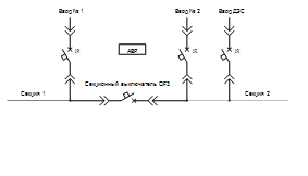
The concept of building schemes ABP This paper presents the circuit diagrams for the three ABP options for entering the reserve:
- Two inputs for a total bus system (primary and secondary);
- Two workers entering into two sections of tires with partitioning; Two working
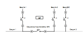
- water into two sections tires plus one water partitioning of DES
- 100630 A series of devices for Compact NS;
- 630 1600 A series of devices for Masterpact NT;
- 1600 3200 A series of devices for Masterpact NW;
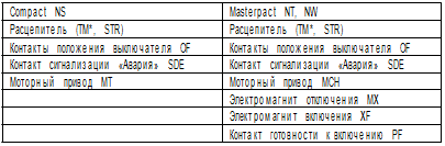
- position monitoring of circuit breakers;
- Setting and changing the exposure time to turn on and off switches;
- Performing self-diagnosis;
- Integration in scheduling;
- change the algorithm of the AVR;
- transmission of information on the status of switches and triggered by the ATS Drugs: GSM, Bluetooth, Internet, Modbus.
2. The algorithm works ABP
Two inputs for a total bus system (main and reserve
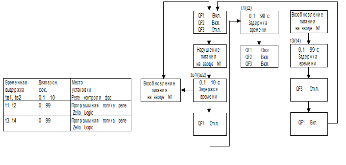
The operation of the control circuit number 1, № 4 "Two inputs for a total bus system (primary and backup) "after power failure
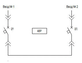
circuit № 1, "Two inputs for a total bus system"
circuit № 4 "how to change the time of the values??"
Two working input c partitioning
[4]The operation of the control circuit number 2, № 5 "Two workers entering c partitioning "after power failure
circuit № 2, "Two workers entering the c partitioning"
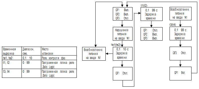
1. Eating disorders on the input
When power failure occurs on the input number 1 to change the position of the relay contacts KV1. After tv1 delay, trip command is issued circuit- switch QF1, section "lost" food. Commanded on the sectional breaker QF3 issued with a time delay equal to t1, when following conditions:b off the circuit breaker QF1 (QF2) section, the "lost" food;
b the voltage level on the section of "lost" power, less than the set point;
b the presence of voltage at the input of the next section;
b no signal input "Blocking switches";
b SA1 mode selector in the "TIA.".
When triggered, the ATS on the door panel, a light signaling:
QF1 «OFF»; QF2 «ON»; QF3 «ON». If the voltage level on the Section's "lost" the power will recover in time less t1, then the command to include the section switch QF3 is issued.
Turn on the circuit breaker QF1 section, which restored food.
2. Restore power to the input
When power is restored to the input, after a time delay t3, BUAVR issues command to disable the section switch QF3. Then the command is issued inclusion of input switch QF1 (QF2) section, which restored food.
With the resumption of normal operation, carried out warning lights on Door panel: QF1 «ON»; QF2 «ON»; QF3 «OFF».[5]
3. Blocking of BUAVR
Start ATS blocked when:
b the circuit breaker manually input N1 or N2;
b when the circuit breaker QF1, QF2, QF3 due to tripping of protection;
b fault in the control unit AVR. In case of malfunctioning of the ABP it is possible to manually disable (enable) automatic switch QF1, QF2 and QF3.
4. Block diagram of the operation BUAVR
circuit № 5 "in violation on the input № 2. algaritm BUAVR similar work "
Two working I c sectioning + input from the DPP
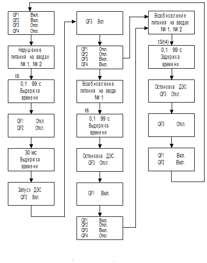
The operation of the control scheme number 3, № 6, "Two workers entering the c sectioning + input from the DPP "after power failure [4]
сircuit № 3 "Two workers entering the partitioning c + input from the DPP"
1. Eating disorders on the input
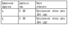
The control algorithm of the AVR voltage failure on one of the business inputs being similar to the type BUAVR AVR.SE2 * BU01 (03), description, see page 10. When power failure occurs on both inputs will change the position of workers relay KV1 and KV2. After the delay time t5, command the circuit breakers QF1 and QF2. Then after 50 ms after control disconnected position switches operating inputs, BUAVR a command to start DES and the inclusion of the section switch QF3. The signal to start DES discrete duration of 1 second. Turning the switch is carried out in the presence of QF4 following conditions:
b Off-breakers QF1 and QF2;
b included sectional switch QF3;
b the presence of voltage at the output of the DPP;
b absence of a discrete signal at the input "Blocking switches";
b SA1 mode selector in the "TIA.".
When triggered, the ATS on the door panel, a light alarm: QF1 and QF2 «OFF»; QF3 and QF4 «On" In the absence of the required level of the output voltage DES for 100 s, after the signal to start DES work scheme ABP stops and signals "Fault DES." [4]
2. Restore power to the input
When power is restored to all operating input to the desired value, Start scheme is "restoring normal" in the ATS unit. After Exposure time t6 the command for the circuit breaker and stop QF4 DES.
When power is restored to the inputs of both working, the command is issued and sectioned off the circuit breaker QF3.
If power is restored only in one of these entries, the command off section switch is issued. BUAVR commands the circuit breaker QF1, QF2, provided that:
b having the required operating voltages on the inputs of N1 and N2;
b circuit breaker will trip QF3, QF4.
3. Blocking of BUAVR
Start ATS blocked when:
b the circuit breaker manually input N1, N2;
b when the circuit breaker QF1, QF2, QF3 or QF4 due protection operation;
b fault in the control unit AVR. In case of malfunctioning of the ABP it is possible to manually disable (enable) automatic switch QF1, QF2, QF3 and QF4.
circuit № 6 "how to change the time of the values"??
4. Block diagram of the operation BUAVR
"When repairing the power to enter № 3. algorithm is similar to BUAVR "
3. Relay monitors its own supply Un
# The relay monitors:
* The correct sequence of the three phases,
* Loss of one or more phases (U measured. <07 x Un)
* Unbalance (adjustable from 5 ... 15% of Un)
* Undervoltage (adjustable in the range of 2 ... 20% Un) (2 ... 12 to 3 x 220-B)
* Increased voltage (adjustable in the range of (2 + ... 20% Un) (+2 ... +10% for 3-220B as max. Voltage 528 V)
# If there is a break or a sequencing phase, the relay opens instantly.
# If there is an asymmetry or drop / voltage spikes, activation (opening) of the relay occurs at the expiration of the time delay set by the user.
# When energisation, the unit remains open [7]
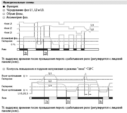
Function diagrams
4.Protokol communication Modbus slave
Modbus Communication Module
The Modbus communication protocol is a protocol such as master / slave (master / Slave)
Modular Zelio Logic smart relays are connected to the Modbus network through the communication module Modbus slave. This module is an electrically non-isolated slave.
Modbus slave communication module must be connected to a compatible modular SR3 B___BD smart relay with supply voltage 24 V
Configuration
Configuring the Modbus slave communication module can carried out:
# Using the keys on the front panel of the smart relay (1).
# Or using a computer with the installed instrumentation system Programming "Zelio Soft 2".
When programming a computer, you can use the language of ladder LADDER diagrams or functional blok_skhem language (FBD).[6]
Example of connection
1- panel XBT N401.
2- Modular smart relays SR3 B___BD.
3- communication module Modbus SR3 MBU01BD.
4- Network Modbus (cable VW3 A8 306R__).
5- junction box TWD XCA T3RJ (with included adapter end line and polarization).
6- bis junction box TWD XCA T3RJ (with included adapter end line).
7- Troynik_razvetvitel 170 XTS 04100.
8- Troynik_razvetvitel VW3 A8 306TF__.
Functional description of the:
1. Modbus slave communication module connected 2_zhilnym or 4_zhilnym network cable Modbus (2).
2. maximum length of network cable _ 1000 m (9600 baud max.).
3. In a Modbus network can be combined up to 32 slave devices or up to 247 slaves devices with the application of repeaters.
4. line termination adapters are installed at both ends of the line (1 nF/10 V, 120? / 0.25 W sequentially).
5. need to polarize the line (470 ohm resistors / 0.25 W) (3).
6. connection cable with RJ45 plug must be shielded.
7. Ground terminal module connects directly to the protective earth in one place on the bus.
Функциональное описание
5. Conclusion
Schemes for automatic transfer switch built on the relay Zelio Logic will provide reliable and uninterrupted power supply to consumers, up to the first category. Besides the installation of such systems will address issues retrofit relevant to the energy system of Ukraine.
.6. References