
Abstract
In carrying out the work were used materials Masters:
Khanin Alexis Research of system control asynchronous motor with asymmetrical cascade multilevel inverter.
Pisanuk Victoria High-voltage electric alternating current with a frequency converter based on current inverter.
Scientific adviser: Shavelkin Alexander
Contents
- Introduction
- 1. The principles of implementation of the active rectifier
- 1.1 The algorithm of the active rectifier
- 1.2 Modeling of the active rectifier circuit
- 2. Stand-alone mode, the inverter current in a sinusoidal voltage source
- 2.1 The principle of self-control inverter current mode sinusoidal voltage source
- 2.2 Modeling of processes in the current stand-alone inverter
- Conclusion
- References
Introduction
At present, the increased interest is the electric induction, performed on the basis of autonomous current inverter with pulse width modulation. This is due to the significant advantages of this type of induction motor drives, the main ones are: first, – the technical simplicity of the implementation of energy recovery mode in the feeding network, and secondly, – the formation of the stator voltage drop with a small amplitude and reduced the steepness of the fronts (compared with widespread asynchronous electric drives based on the autonomous voltage inverter with pulse width modulation).
Rationale for master's thesis topic: The question of resources and energy are directly related to the introduction of high-frequency control for a specific electric power. In this regard, there is actual improvement in performance drives with frequency converters.
The main issues to be decided in the work:
1. The principles of implementation of the active rectifier
At the moment, to semiconductor frequency converter (imposed strict requirements on the quality of the input current consumption of the AC [1]. Regarding frequency converters on the basis of autonomous voltage inverter, these requirements can be met by using an active rectifier voltage, which ensures the formation of nearly sinusoidal current using a pulse-width modulation. When used in stand-alone inverters circuit current inverter is the same problem occurs with the formation of the input current. Its solution is possible when using an active rectifier.
The purpose of the work. Develop an algorithm implementation using AVT relay input current regulation principle and thus perform modeling of processes in distillation scheme.
1.1 The algorithm of the active rectifier
AVT is a three-phase bridge rectifier (TMB) to fully manage keys with unidirectional conductivity (lockable by the control thyristors in Fig. 1) and is connected to AC power via LC - filter ( L IN, CIN ). Choke in the load circuit Ld specifies the mode of operation of the power supply.
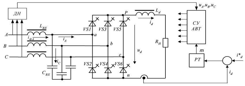
Figure 1 – Block diagram of AVT
Powered AVT mode controlled DC formation of the active current drawn from the AC source. It provides an adjustable output voltage is lower than the voltage for unmanaged TMB and operates at a constant direction of the rectified current, but allows changing the polarity of the rectified and EMF.
Work has AVT features. For the current flow in the two input phases in the scheme AVT open on one key in the two arms, in a disabled state (input current is zero) - unlocked two keys in one arm to close the current in the load circuit with an inductance. Possible states of the circuit AVT shown in Table 1 displays the phase where the networks that are connected to the terminals p and n (Fig. 1), the rectified voltage U B , currents in the phases of the network and the angle of the space vector of the current shift.
Таблица 1 – Возможные состояния АВТ.
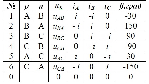
Then obtain six non-zero vectors and three zero when disconnected from the mains rectifier and closed both keys in one of the arms of the scheme. The spatial position of the current vector are shown in Fig. 2a. In this case, the numbering of the provisions of the vector corresponds to Table 1. Consider the case where cosφ = 1 and the space vectors of voltage and current are in phase with the network. We divide the period into six intervals respectively moments of polarity reversal phase voltage network. In this phase intervals correspond to the maxima voltage and determining the spatial position of the voltage and current vectors in the sector of 60°.
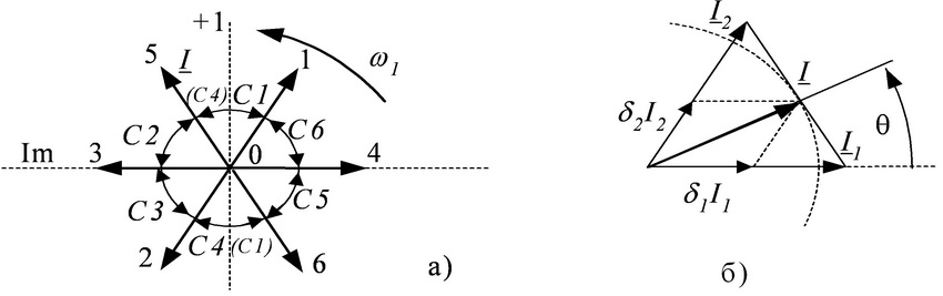
Рисунок 2 – Формирование пространственного вектора входного тока.
to determine the relative (to the modulation period T, corresponding to the time spent in a certain position vector) length of time the scheme in states that provide a synthesized form a rotating space vector I (with the path that approaches in circumference) for the sector 60 ° (Figure 2b) can use ratios:
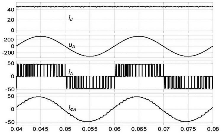
δ1=μsin(60 - θ); δ2=μsinθ; δ0=1 - δ1 - δ2 , where θ - the angle of rotation of the synthesized vector, θ1, θ2, θ0 - relative duration (to T) location scheme in the states corresponding to non-zero vectors I1 and I2 and zero when AVT is unplugged, the interval T corresponds to 1, μ=(1 - 0) - the modulation amplitude (defined as μ=Id/IdMAX ). current waveforms i d, iFA, iA and phase voltage network UA are shown in Fig. 3. Figure 3 – Waveform voltage and currents at ƒM=3000 Hz, and μ=1. Electric drive is an integral part of conservation. This is largely for AC Motors High Power, which uses high-voltage induction motors. At the same time come to the fore issues of quality power conversion and inverter are increased requirements [1]. For high-voltage electric alternating current "classical" solution is the use of cascade multilevel inverters such as «Perfect Harmony», where the scheme is quite complex, and at a voltage of 6 kV single-phase contains six independent inverters voltage at the output stage. The input circuit contains 18 rectifiers with capacitive filters, which are powered by a transformer with 18 sets of secondary windings. A more simple and promising solution in terms of obtaining a sinusoidal voltage output is possible on the basis of autonomous current inverter with an output capacitor filter using a pulse-width modulation [2 – 4]. The more that the form of a sinusoidal voltage is provided close to the entire range of output frequency regulation. There are solutions of high-frequency converters based on the autonomous current inverter [3], which are quite successful in competition with multi-level inverters, for example, Power Flex 7000 (firm «Rockwell Automation"). The structure of the power circuits of frequency converters on the basis of autonomous current inverter in conjunction with an active rectifier is much simpler than the multi-level inverters. The scheme of the autonomous current inverter performed on locked by the control circuit thyristors with large losses in the switch. This limits the output current of the formation of an autonomous current inverter. To reduce the number of switches used by the election of pulse-width modulation [1] with the suppression of higher harmonics (5th, 7th, 11th) in seven half-wave pulses in the inverter output current is independent of current. At the same time according to [1] Harmonic (THD) of output current autonomous current inverter is overvalued and is about 5%. Slightly better performance for the output voltage and current autonomous current inverter are obtained in [3, 4] using the relay controller to generate the load current. Known solutions applied autonomous current inverter [2 – 4] focused on the formation of the current. However, the question of autonomous current inverter as a source of sinusoidal voltage at a given time is insufficiently studied. Simplify the problem of high-power applications with frequency converters according to quality of output voltage and input current standards [1] at this time is important. Her decision will help to expand applications of high-frequency converters. At the same time promising is the use of frequency converters on the basis of autonomous current inverter and low voltage electric drive, where they may be able to compete with the "classical" solution based on a two-level inverter with active voltage rectifier. The purpose of the work. Develop principles of autonomous current inverter mode sinusoidal voltage source.
This should solve the following problems:
1.2 Modeling of the active rectifier circuit
2. Stand-alone mode, the inverter current in a sinusoidal voltage source
2.1 The principle of self-control inverter current mode sinusoidal voltage source
three-phase bridge circuit to AIT locked by the control keys with unidirectional conductivity (Fig. 4) includes an output filter capacitor of higher harmonics. Regardless of the AIT algorithm outputs a current iI pulse shape, which is the sum of the currents capacitor iC and load iN (iI=iC+iN). In the paper [6] The principle of generating a voltage with three relay voltage regulators (IGR), which provides high quality output with a minimum of AIT switching key scheme.
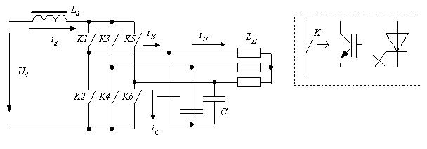
Figure 4 – The structure of the power circuits of AIT
This PPH phase signals form the key management in the shoulder AIT P N, ensuring the flow of the output phase current pulses AIT positive and negative polarity . The momentum distribution is carried out in accordance with the tact of the scheme. Clocks (6 per period) are determined by the 1st harmonic current iI, which lags the voltage by an angle β. The need to identify β - lack of solutions.
Figure 5 – Vector diagram of the output phase of the AIT
AIT control algorithm, which uses only the reference signal on the output voltage of the AIT. Thus at any given time is only one phase in the PPH, which voltage deviation from a predetermined voltage value to the greatest active time. To reduce the number of keys used three-level switching voltage regulator relay.
also proposed for stable operation of the system during the formation of a voltage signal AIT use the correct current input.
2.2 Modeling of processes in the current stand-alone inverter
Simulation of the proposed solutions performed using the software package MATLAB. The structure of the model AIT with an active rectifier (AUT) at the input includes: a source of input voltage, the input filter AVT AVT system management and AIT, CAP AUTO with PI - current regulator, compensation unit assignments AIT, active-inductive load Z H=10Om, cosφ=0.8. Capacitance of the output filter C=115uF (QC=0.6 QL), Ld=20mGn. Deviation (delta) for PPH δ=5% of the desired amplitude of the voltage phase load. The oscillograms of the output voltage AIT ua, current id, the output phase current AIT i And , the phase current load ia, as well as the voltage for the key K1 are shown in Figure 6 at f2=50 Hz. When set Id=(1-1.25) IDmin harmonics (THD) voltage AIT (taking into account harmonics up to order 40) THD=3.06-3.57%, the switching frequency of the key AIT fP=650-1300Gts. At the same current load and f2 =25 Hz (halving the voltage (U/f=const) and ZH=5 ohms, cosφ=0.8) for δ=5% THD=3.39-4.18%. The value of the switching frequency increased fP=1300-1600Hz. Meaning fP can be reduced by increasing δ half (10%) - in this case fP=650-1200Gts, but slightly increases THD=7.01-6.5%.
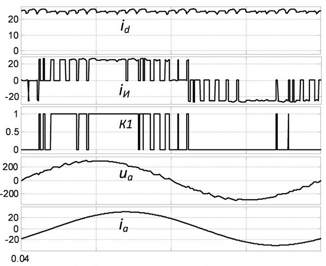
Figure 6 – Waveform of output voltage and current AIT.
An important advantage of the use of the principle of generating a voltage relay AIT is that the quality of working off the voltage is virtually independent of the current ripple id. This reduces the inductance of the mains reactor Ld. However, the control scheme is desirable to use AVT astatic the average value id system of regulation (SAC).
Conclusion
The principles of implementation of the active rectifier using relay controls the input current. The model and simulation results of the active rectifier circuit in the software package MATLAB.
The principles of the implementation of autonomous inverting current mode sinusoidal voltage source using the principles of relay control. The scheme of the model and the simulation results in the inverter circuit software package MATLAB.
The subject of research dalnejshem javljaetsja Creative CAP structure prymenytelno asynchronous EP with vektornыm management.
Important notice
In writing this essay master's work is not yet complete.
Full text of the work and materials on the subject may be obtained from the author or his head after that date.