
Abstract
Content
- Introduction
- 1. Theme urgency
- 2. Goal and tasks of the research
- 3. Review of research and development
- Conclusion
- References
Introduction
In recent years, voltage instability of large power systems of the world has led to a number of expensive power cuts. Accidents in Europe, America and Asia - in France in 1978, Belgium in 1982, in Sweden in 1983 and 2003 in western France in 1987, in Tokyo in 1987, in Sao Paulo in 1997, Greece in 2004, in northern Ohio, Michigan, New York and Ontario, in August 2003, in Moscow, Moscow and Kaluga regions in May 2005... Almost all accidents and power cuts were caused by a violation of the energy balance, both active and reactive power to a greater extent responsible for the stability of the voltage on the topic of public networks and distribution networks of electricity consumers. It is an increased density of reactive power flows in the distribution network is the most negative consequences in terms of voltage drop during heavy loading conditions (very hot or very cold weather), which often leads to the collapse of the voltage - an abnormally low or zero line voltage [1].
Burshtynska TPS is a "window to Europe" for Ukraine, and it’s already working in the European energy system. So then, it is important not only for the DTEK company, but for the All-Ukrainian energy sector. Also working on the European energy market requires Burshtynska TPS high competitiveness and performance of environmental requirements [2]. Thats why there is a need to explore ways to control reactive power in the Western Burshtynska TPS power system. So, the stable work of this power station is very important.
1. Theme urgency
The most complicate problem of power supply networks of today was an increase in the consumption of reactive power on the background of the extreme complexity of its transfer of power to consumers. In this regard, the implementation of measures is to compensate reactive power from consumers themselves, thus preserving the overall balance of power in the system and ensure the stability of the supply voltage [1].
At the moment there are a number of ways to control reactive power. There are entirely new ways of monitoring power mode, such as, real-time assessment must be conducted mode power system for optimization of reactive power and voltage using the PMU [4].
Master's thesis is devoted to the study of these processes in the part of a real power system in Burshtynsk TPS, the appropriateness of their use, the modeling of situations lead to a redistribution of reactive power.
2. Goal and tasks of the research
The goal of the master's work - is the development of a mathematical model of the power grid in the area Burshtynsk YPS to investigate different ways to control the reactive power
The main objectives of the study:
1. Analyze the existing power supply network area (the main power line).
2. Determine the electrical load of consumers and make an equivalent circuit network
3. Selection of optimal operating conditions and ES lines
4. Present the reactive power balance and to identify ways of its regulation.
3. Review of research and development
Transmission of electricity from generators to consumers is a complex physical process. Reactive power does not perform useful work, and only determines the speed of conversion of electrical energy into a magnetic field and vice versa, i.e. rate of energy exchange between the generator and the magnetic field receiver power. Generation of reactive power does not require a direct fuel, but it causes the network transmission costs in the form of active energy losses of electrical energy and further network elements of the electrical loads, reducing their total capacity. [5].
Active power generated by the generator and is determined by current power frequency 50-60 Hz located in phase with voltage. Reactive power is consumed by the formation of the electric and magnetic fields in the power lines, transformers, motors, capacitors and other equipment produced by synchronous generators with active power and an increase / decrease in the consumption of reactive power at full rated power of the generator leads to the opposite decrease / increase in the proportion of active capacity.
Reactive power compensation is possible because the current in the inductive reactive power consuming equipment (asynchronous motors, transformers, electric installation, valve transducers, etc.) lags the voltage on phase, while condensing units, synchronous motors are different currents lead the voltage in phase. Capacitive currents in the capacitor units and reactive power, which creates an electric field in the capacitor banks in the direction opposite to the inductive currents and reactive power, creating a magnetic field in the windings of transformers, motors, etc. As a result, the reactive power capacity eliminates the reactive power of the magnetization and the network is unloaded from the reactive power flows, increasing its capacity and stabilize the supply voltage [1].
The increase in the issuance of reactive power generator in order to deliver it to the customer is impractical, it is clearly demonstrated in Fig. 1
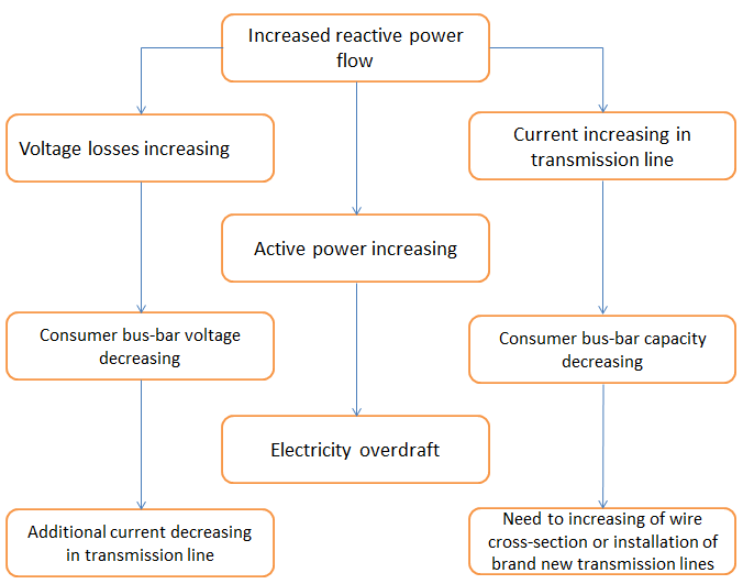
Figure 1 –The consequences of the increased flow of reactive power
The most effective way to reduce losses in electric networks is to compensate the reactive power of consumers.
The development of satellite communications systems GPS (USA) and GLONASS (Russia) and others led to the creation of WAMS (Wide Area Measurement System)-a large-scale data collection system of the new generation of measuring equipment PMU (Phasor Measurement Unit). PMU, set in the node measures the magnitude and phase node voltage, the currents in modules and lines of incident angles between current and voltage.
The combined collection system measurements - WAMS, PMU sensors give a real picture of the dynamic state of the power system: WAMS-technology is to organize the PMU by calculating the mutual angles of the vectors of voltage and current in a clearly defined points in time by synchronizing with an accuracy of 1 microsecond measurements carried out by them.
The result is an objective picture on the EPS as a whole (for example, you can uncover hidden reserves of power) that allows you to specify the model of the transition process, which leads right choice of control actions. As a consequence, real-time assessment must be conducted mode power system for optimization of reactive power and voltage [6].
Further it is necessary to characterize directly the object of study (Fig. 2)
Figure 2 –Burshtynskaya TPP
(Animation: 5 shots, 5 cycles of repetition, KB)
(1 - general view, 2 - schematic representation of lines, 3 - the first stage of the integration of the energy system in Europe, 4 - geolocation, 5 - bird's-eye view, size 142 KB)
Burshtynskaya TPS (a division of "Zapadenergo") is located at a distance of 6 km to thenorth-east, the Burshtyn Galician district of Ivano-Frankivsk region, on the right bank of the reservoir on the river Gnila Lipa.
The positive dynamics of growth in the consumption of electric energy in an area where the thermal power plants, which in turn is an important element of the coating load power district [6].
Characteristics of existing transmission lines
In the area of Burshtyn TPP includes such lines as Western Ukrainian, Kalush, Stryi, Borislav, Chernivtsi, Mukachevo, Albertirsa. The brief description of the major lines:
The most problematic line is the PL-400 kW connection - Mukachevo. The line is the longest lines that radiate outward from the station and passes it through the mountains. As for the control of reactive power, then the cogeneration control of reactive power support given Western power grid voltage level on the tires of OSG 220 kV and 330 kV.
When you disconnect the line, more than 220 kV line loaded connection - Stryi A and cogeneration - Stryi B, which is also a substation stry on two lines stry-Mukachevo have a connection to the substation Mukachevo.
Conclusion
The issue of power control Burshtynsk TPP is very important. In addition, the fact that at the moment this is a backbone station in western Ukraine, and the most important line is the most problematic in the coming years will be the reconstruction and replacement of the power to fundamentally new. The projected increase in capacity - 800 MW, accounting for over 35% of installed capacity. All this may lead to a power distribution system. Reactive power control, in turn, is a prerequisite for reliable and quality power supply that in exports of energy in the power system in Europe - is paramount.
In writing this essay master's work is not yet complete. Final completion: December 2013. Full text of the work and materials on the topic can be obtained from the author or his specific adviser after that date.
References
- По материалам завода «Нюкон». Стабильность напряжения электроэнергетической системы [Электронный ресурс]. – Режим доступа: http://www.elec.ru...
- Портал ДТЭК. ДТЭК Бурштынская ТЭС: подготовка к работе в условиях европейского энергорынка [Электронный ресурс]. – Режим доступа: https://portal.dtek.com...
- Минин Г.П. Реактивная мощность / Минин Г.П.– М.: Издательский дом «Энергия», 2007. – 53-58 с.
- Дементьев Ю.А., Бердников Р.Н., Моржин Ю.И., Шакарян Ю.Г. Концепция интеллектуальной электроэнергетической системы [Электронный ресурс]. – Режим доступа: http://www.ruscable.ru...
- По материалам завода «Нюкон». Концепция реактивной мощности, основные виды компенсации [Электронный ресурс]. – Режим доступа: http://www.elec.ru/...
- Глазунова А.М.. Диссертация на тему «Развитие оценивания состояния электроэнергетической системы на основе интеграции данных SCADA и PMU» [Электронный ресурс]. – Режим доступа:http://www.dissercat.com...
- Техніко-економічне обгрунтування повузлового технічного переоснащення ВРП 220/330/400 кВ Бурштинської ТЕС.