
Abstract
Contents
- Introduction
- 1. Ground fault in the three-wire networks 6–10 kV
- 1.1 Consequences of the metal ground fault
- 1.2 Relay protection from the ground fault
- 2. Calculation and measurement of ground-fault currents
- 2.1 Calculation of ground-fault currents
- 2.2 Measurement of ground-fault currents
- 2.3 Oscillography of ground-fault currents
- Conclusion
- References
Introduction
On the industrial enterprises networks 6–10 kV are performed with insulated neutral. In these networks, the ground fault is not short, that is why at such damage it is possible some time to continue work. However, with the circuit voltage on the insulation of uncrippled phases and impulsive overstrains through the arc rise . The overstrains can cause the hasp of insulation on other phase, that results in the flowline of large currents of the double ground fault. An arc can cause burning down of cables and iron of engines. For estimation of influences of ground-fault currents, the necessity of their compensation needs to know the values of ground-fault currents. Practical actuality of work is conditioned to these.
In planning the ground-fault currents are determined by the calculation without taking into account transitional processes causing the impulsive overstrains. Scientific actuality of the work caused the need to develop methods for the experimental analysis of ground-fault currents. In this connection it is necessary to decide the following tasks:
- to execute the oscillogram digitization of current and voltage of the metal and arc ground fault;
- to develop a dynamic model of oscillograph galvanometer (OG), which was used in oscillography;
- to execute correction of oscillograph dynamic error;
- to develop the mathematical model of the metal ground-fault current.
The results will be used in the learning process and transferred to PJSC Concern Stirol
(Gorlovka), where oscillography was executed.
1. Ground fault in the three-wire networks 6–10 kV
1.1 Consequences of the metal ground fault
6 kV power supply system is the IT system with insulated neutral. For evident we will consider the connection of the secondary windings of power transformers at the factory substations (SS) into a star (fig. 1.1).
Figure 1.1 – The metal ground-fault of phase C
(animation: 9 frames, 5 cycles of repeating, 25,8 kilobytes)
Each cable conductor (or phase of motor) has a capacity of Ci insulation in relation to ground. In normal mode capacities are connected in a star. Phase voltages in relation to ground depend on the value of capacities. If they are identical, the voltage of every phase is equal to the phase: Up = 6 / √3 = 3,46 kV. If the insulation of one phase is reduced, the voltage in relation to ground will be less than the phase and the other phase voltage exceeds the phase.
At the metal ground fault transitional process which lasts about a quarter of the period approximately flows in the first moment (5 ms) and then the set mode comes.
There are large throws of current and impulsive overstrains in transitional mode. Because the duration of the transitional mode is very small, the throws of current do not cause the overheat of the damaged cable. However, much the overstrains can cause the hasp of isolation in any other point of network. This double ground fault is close to the two-phase short-circuit, and if it will not be disconnected by relay protection, will cause an impermissible overheat in points circuit.
In the set mode in connection with the large insulation resistance fault current IC is very small as compared to the operating current. Ground potential becomes shutting phase, therefore voltage on the capacity of this phase is equal to the zero, and on the capacities of insulation of other phases increases to linear. Accordingly the current to the windings of the transformer flows through the insulation of uncrippled phases, ground, fault point (fig. 1.1). The current, mainly, is capacitive.
1.2 Relay protection from the ground fault
We will consider protection with the use of voltage transformer VTOI.
For ease of analysis the asymmetrical system is represented as three systems: direct, reverse and zero sequences. Direct sequence voltages U1 are identical on a value, phase-shifted by 120° with alternation of the A–B–C phases (fig. 1.2,a). Reverse sequence voltages U2 also form a symmetrical system of three-phase vectors, but with alternation of the A–C–B phases (fig. 1.2,b). Zero sequence voltage vectors are the same in value and direction U0 (fig. 1.2,c).
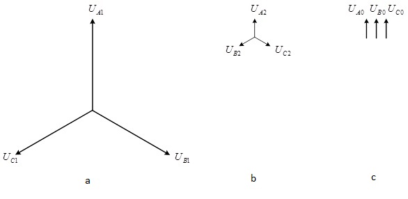
Figure 1.2 – Direct (a), reverse (b) and zero (c) sequences
In the case when between a transformer neutral and the ground there is an electrical connection, currents of the zero sequence flow I0 under the influence of voltage U0. The high-voltage winding of VTOI is connected in a star with the grounded zero, so there is the circuit for the flow of the current I0.
For implementation of relay protection [7] used the secondary winding VTOI, connected in open delta (fig. 1.3). At ground fault in each winding of the high-voltage, which are not shown on the figure, the currents I0 identical on a value and direction flow. They create the magnetic streams of zeroing sequence, which lead to the secondary windings of the voltage U0. These voltages are added up arithmetically, therefore there will be the voltage 3U0 on the voltage relay RV.
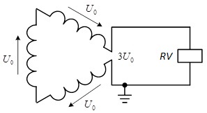
Figure 1.3 – Diagram of relay protection from ground fault with the use of VTOI
This protection is unselective, because only fixs the short to ground, but does not determine the location of shorting. Therefore it operates on the signal, but not disconnection.
If after the signal by inspection it is not succeeded to find the place of shoeting, for its discovery by turn disconnection of cable busses will be required – until will not disappear 3U0. Such disconnection of uncrippled lines violates a basic requirement for the system power supply – uninterrupted power supply, so in addition to the described protection must be provided selective protection of connection.
2. Calculation and measurement of ground-fault currents
2.1 Calculation of ground-fault currents
The metal ground-fault current in the set mode settles [1] calculated in planning.
For approximate calculations in [1] a formula is recommended for a capacitive current in A
where U – linear voltage in kV, l∑ – the total cable length in km. Putting here the value of 6 kV, we will get
where the coefficient 0,6 has the A/km dimension.
Research carried by Ph.D. L. Dudarev have shown that this formula gives lower results. He proposed a formula
which is at the voltage 6 kV takes the simple form:
For exact calculations the specific capacitive currents of the cables Is in A/km, which depend on the cable cross-section F (table 2.1).
Table 2.1 – Specific capacitive currents of the cables [1]
| F, mm2 | 25 | 35 | 50 | 70 | 95 | 120 | 150 | 185 | 240 |
| Is, A/km | 0,47 | 0,54 | 0,63 | 0,73 | 0,85 | 0,95 | 1,07 | 1,18 | 1,31 |
Regardless of how the cables are connected (in series or parallel), the capacitive currents from all cables are added up, because the capacities insulation in relation to the ground are always connected in parallel.
We denote by j number of cable at their numbers n. At ground fault a cable creates a capacitive current
Capacitive current from n cables
According to the three pairs of values of power and capacity we will get approximating expression
for the Cm capacity in mkF three phases of motors 6 kV with the total nominal power Рn∑ in MW.
Capacitive current from motors 6 kV
where ω = 100π – angular frequency in rad/s. When U = 6 kV
The total capacitive current
The calculation of transitional processes in the initial period of time and at burning of arc practically impossible.
2.2 Measurement of ground-fault currents
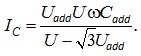
A method of creation artificial capacitive asymmetry [1] consists in connecting a one-phase capacitor Cadd between one of the phases and ground. The value of this capacitity in mkF
The voltage Uadd is measured between a phase with an additional capacity and the ground, which allows to determine the groung-fault current
This method is applicable in networks with arc suppression reactor (ASR) and without it. Another methods are used in networks with the ASR. The method of displacement of neutral consists that consistently with the ASR the transformer neutral displacement included (2 kVA, 220/400), which is powered from the mains voltage of 220 V. The measured zero sequence voltage U0 (on neutral) and the current I0, flowing through the ASR. Setting of the ASR should be as close to the resonance. Capacitive ground-fault current
2.3 Oscillography of ground-fault currents
For the receipt of information about transition modes and exact values of the fault current in the experiments it is expedient to execute oscillography instantaneous values of iз fault currents if, u0 voltage of zero sequence and even one tension of uncrippled phase in relation to ground.
Oscillography is desirable to execute by digital oscillograph. If a galvanic oscillograph is used, oscillograms will be recorded in high dynamic error that should be corrected by the method described in [6]. If at digital oscillography the inertial current and voltage sensors are used(including measuring transformers), the dynamic error is corrected with the use of the expression (6) from [6].
The initial data we have used some results of the experiment ground fault of phase C at SS 123 when the ASR switched. The metal ground-fault current has been oscillographed.
Fig. 2.1 shows the oscillogram without the dynamic error correction. It allows you to execute a qualitative analysis of the initial period of the groung fault and quantitative analysis of set process of groung fault, in which the error is small.
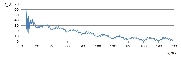
Figure 2.1 – Oscillogram of current of the metal ground fault mode on SS 123 without the dynamic error correction
The first task – to find an analytical expression for the currents of the metal ground fault. On the oscillogram can be divided into three areas of process i(t). In the first area – from 0 to ≈ 15 ms – there is a pronounced high-frequency component. The second area – from 15 to ≈ 160 ms – pronounced exponent to which the non-sinusoidal component superimposed on the periodic appearance. Over – the set periodic sinusoidal process with a cycle time 0.02–seconds.
In accordance with it a next method of treatment is offered. In the beginning set constituent appears as the sum of harmonics. The next stage – the selection of exponent for the second area of the process (fig. 2.2), where R2 – value of authenticity of approximation.
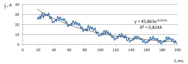
Figure 2.2 – The selection of exponent
The analysis shows that the difference between if(t) and the exponent gives is(t). The last step – count a high frequency component ihf(t).
In work it is also planned to execute the analysis of ostsyllogram at experience of the arc ground fault.
Conclusion
- Method of prognostication of capacitive currents used in planning in networks 6–10 kV does not give objective information about the value of currents and special about transitional processes.
- Implementation of experiments of the metal and arc ground fault is needed for the ground of necessity and estimation of efficiency of ground-fault currents compensation.
- Oscillograph galvanometers bring in a dynamic error in results of oscillography. For its compensation it is necessary to execute correction of measurings, considering a galvanometer the aperiodic link of the first order.
- A mathematical description of the metal ground fault invited to execute in stages. In a set mode the process of change of current is represented as a Fourier series. After subtraction of this process from adjusted ground-fault current oscillogram transition process it is expedient to approximate the sum of exponential and exponentialsinusoidal functions.
- The mathematical description allows to develop the dynamic model of the network as elementary links and also execute their parametric identification.
This master's work is not completed yet. Final completion: December 2013. The full text of the work and materials on the topic can be obtained from the author or his head after this date.
References
- Справочник по электроустановкам высокого напряжения / Под ред. И.А. Баумштейна и В.М. Хомякова. – М.: Энергоатомиздат, 1989. – 656 с.
- Правила устройства электроустановок. – М.: Энергоатомиздат, 1985. – 640 с.
- Правила устройства электроустановок. – Х.: «Форт», 2009. – 704 с.
- Лихачев Ф.А. Замыкания на землю в сетях с изолированной нейтралью и с компенсацией емкостных токов. – М.: Энергия, 1971. – 152 с.
- Неклепаев Б.Н., Крючков И.П. Электрическая часть станций и подстанций. – М.: Энергоатомиздат, 1989. – 608 с.
- Куренный Э.Г., Дмитриева Е.Н., Вальков Н.Г. Динамические погрешности осциллографирования электроэнергетических процессов и их коррекция // Энергетика и электрификация. – 1997. – №3. – С. 33-36.
- Чернобровов Н.В. Релейная защита. – М.: Энергия, 1971. – 624 с.