
Abstract
Contents
- Introduction
- 1. Topicality
- 2. Review of existing types of protective relays
- 2.1 Current protection, reacting to the current value of the total residual current of industrial frequency
- 2.2 Protection responsive to the components of the power frequency current and residual voltage
- 2.3 Apparatus responsive to the current components and the zero sequence voltage transient
- 2.4 Protection, locking cash current with a frequency that is different from industrial
- 2.5 Protection responsive to high–frequency components in the current zero–sequence occurring naturally
- 3. Main content
- Findings
- References
Topicality
6–10 kV networks account for about 80% of the total length of all lines in the Ukraine. The vast majority of these networks is used to power large–scale production of electric motors, transformer rooms and consists of a cable transmission lines, which are operated in the most difficult conditions, ie they are affected by humidity, extreme temperatures and high voltage spikes caused by switching processes or Single phase to ground (SPG). Recent most influence on the condition of the insulation of cables and electrical equipment connected to them because they are the most common type of injury in isolated, compensated or resistance–grounded neutral 6–10 kV. The most common type of SPG is an arc. The long–term course of SPG arc occurs when nuisance tripping faulty feeder protection relay, and, in most cases, is the cause of interphase faults (according to the operational experience of about 60–80% of the single–phase faults develop in interphase ), which often leads to fire cables [4] and is accompanied by great economic losses.
The analysis of known methods of protection SPG [1–3], it follows that in practice there is no sufficiently reliable way to protect networks with small total earth fault current.
Typically, in the auxiliary power stations or other networks, characterized by low total current SPG (to 10A), exposure single–phase ground fault can be up to four hours [5], during which the network–connected electrical installations are significant overvoltages sometimes can reach 3–3,9 Ufn. In networks with a total capacitive current SPG above 10 A in responsible feeders recommended installation of relay protection of SPG, acting on the feeder off with time delay of 0.5 s [6]. Is known that 0.5 enough to cause multiple overvoltage and thus to insulation breakdown electric cable transmission or attenuated in most places.
According to the [7] and [8], to improve the reliability of the network is proposed partial neutral ground network using a 100 ohm resistor installed in the transformer neutral. It is assumed reduction in surge to 2.2 – 2.5 Ufn and increase the sensitivity coefficient of relay protection by the appearance of an additional component of the active current. However, as it turned out [9], this innovation increases the duration of the arc SPG and complicates the design of the network due to the need to install a resistor.
1. Topicality
Disorders of the network associated with SPG, in most cases are due to the insufficient sensitivity of the protection relay, and as a result, nuisance tripping faulty feeder, which can lead to electric shock to persons. Disrupt the production process companies can also nonselectivity operation of relay protection, as is the case in networks with significantly different in size capacitive currents own connections.
Because of the complexity of the field experiments to determine the most effective way to protect during arcing faults on the ground, is the actual analysis of the various types of relay protection and surge suppression equipment with the help of advanced mathematical models
2. Objective and tasks of the research
Currently, the following basic types of protection from SPG.
- Protection, which measure the residual voltage.
- Non–directional, recording component–frequency residual current.
- Directional protection responsive to constituents–frequency current and residual voltage.
- Security locking "imposed" current with a frequency different from the industrial.
- Protection responsive to high–frequency components in the current zero–sequence occurring naturally.
- Protection responsive to the components of the current and residual voltage in the transition process SPG.
2.1 Protection, reacting to the current value of the total residual current of industrial frequency
This protection can be built using the body as a measuring current electromechanical relay–type PT–40, an analog switch type РТЗ–51 or a member of the terminals of relay protection, such as blocks microprocessor protection БМРЗ НТЦ «Механотроника», terminals protection SEPAM type S20 company Schneider Electric and others. Selective operation of such a protection mode insulated neutral may be provided only in those cases where the total capacitive current network ІСS (the lowest of all the possible modes of operation of the network) is substantially greater than its own ISmah capacitive current line (if the external SPG).
This type of protection may not always provide the selectivity of a network with isolated neutral, especially in networks with unstable primary network diagram, periodically changing the values of their own line of capacitive currents and the total capacitive current, as well as in a network with a small number of lines [1].
However, a relatively simple and cheap non–directional current protection have their uses.
2.2 Protection responsive to constituents–frequency current and residual voltage.
Consider the principle of action of this class of protection relay for example ЗЗП–1М
This protection is designed to selectively disable lines 10 kV single–phase ground fault and can be used in networks with a total capacitive current of at least 0.2 A, as indicated in the manufacturer's information. However, such data only mislead designers and customers protection devices, since it does not take into account the actual operating conditions [2]. In connection with a high probability of occurrence of single phase earth faults in BL 10 kV through the transition resistance and in view of a supply device for the application of sensitivity ЗЗП–1М useful in those networks 10 kV, wherein the minimum value of the total charging current of at least 2,5 – 3 times higher, ie, 0.5 – 0.6 A.
Current protection circuit ЗЗП–1М are connected to a cable current transformer (Fig. 1 a), and therefore protected by air line should have a cable box. This is a drawback of protection ЗЗП–1М, limiting its use.
Voltage circuit protection ЗЗП–1М included in the residual voltage 3Uo, derived from the special voltage transformer connected in open delta. For the protection of the relay from the higher harmonics, the device connects through a filter with a resonant frequency of 50 Hz, which suppresses all higher harmonic components. To eliminate the harmful effects on the device ЗЗП–1М surge in the scheme. A short delay in the supply voltage with a maximum voltage relay 1РН type РН–53/60D set point lower than the voltage switching device. As can be seen from the diagram, the voltage applied to the device 3u0 ЗЗП–1М only after the relay 1РН and closing its contacts.
Schematic diagram of the inclusion of directional type ЗЗП–1М ТН – voltage transformer type НТМИ; ТТНП – current transformer cable type, ВУ – accessory of protection from higher harmonics.
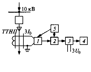
Figure 1. Block diagram directional –type ЗЗП–1М
Protecting ЗЗП–1М includes the following main bodies: the matching device 1, AC amplifier 2, a phase–sensitive amplifier (organ of power direction) 3, 4 relay output and power supply unit 5 (Fig. 1). Feeder type БПН–111 is connected to a voltage transformer or auxiliary transformer substation.
When a single–phase ground fault, the capacitive currents Ic, determined capacitance lines intact phases to ground are conditional direction to the fault on the affected lines and thus directed in various ways on the damaged or entire lines. On the undamaged lines at the direction of the currents from / to the buses 10 kV substation protection ЗЗП–1М fail. On the faulty line with the direction of the total capacitive current ІСSfrom tires substation to the fault protection ЗЗП–1М is triggered if the value of the total current is greater than its current operation. If we assume that the average specific value of the charging current for the 10 kV overhead lines is 1 km 0.025 A, for the reliable operation of protection ЗЗП–1М at its minimum setting of 0.2 A (primary) requires that the total length of all lines intact 10 kV this network would be not less than 20–25 km and, respectively, the total capacitive current ІСS= 0.5–0.6 A. In modern electric systems 10 kV, this condition is normally provided, but in the case when one or Two lines can be turned off and the protection of ЗЗП–1М will not be able to work off because of insufficient value of the total capacitive current required that in addition to the straight–line defenses (ZZP–1M) in the substation would be set back–nonselective maximum protection mode voltage (relay 2RN in animation), which delayed 0.5–0.7 with acts to disable the supply transformer (in this case should be prohibited actions include automation: ABP, AПВ).
2.3 Apparatus responsive to the current components and the zero sequence voltage transient
Devices that respond to the components of the current and residual voltage in the transition process SPG. The principle of operation of data protection is based on the control of the propagation direction of the current and voltage transient arising from the SPG and extending to the ends of the lines (points of protection settings), and consists of a comparison of the original characters and memorizing the current 3I0 and 3U0 voltage in circuit. When the signs of SPG is fixed in the protective direction, and a mismatch detected external SPG. Fact circuit controlled actuation trigger body 3Uo steady–state voltage of industrial frequency.
The best–known developments aimed pulse SPG protections include:
- autonomous devices designed wave–type protection ИЗС and УЗС–01, developed ЭНИН;
- centralized directed signaling device SPG (ЦНУСЗ) " Импульс " is designed and manufactured ИГЭУ;
- autonomous device directional type КЗЗП developed in the Donetsk Polytechnic Institute of Microelectronic and its analogue – the device type ПЗЗМ developed now НТБЭ (Yekaterinburg).
The scheme of the device is connected УЗС is shown in Fig. 2. Circuit connected to the current transformer cable line or neutral current transformers three–phase cables or overhead power lines. The voltage connected to the open delta winding of the voltage transformer section of tires, which is connected to the line, and in the absence of these windings – to a common point of three 4.10 uF capacitors connected in star and connected to the phase windings of the transformer secondary voltage to neutral of these windings .
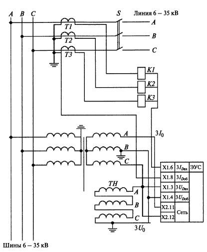
Fig 2. Circuit diagram of the device is connected УЗС; T1–T3 – current transformers K1–К3–load current transformers; S– breaker high–voltage lines.
The above autonomous and centralized device for protection against SPG only respond to the electrical values retransient process and therefore does not have the property under steady continuity of earth faults. The property concontinuity of action for damages must be sustained, above all, for the defense to the action on the trip (for example, to simplify the coordination of protection tripping times, take into account that the voltage does not immediately disappear off the network after the damaged section). When the anti–SPG with the action viem to signal the continuity of action makes finding the damaged area by operating switches in the network.
2.4 Protection, locking cash current with a frequency different from the industrial
The principle of operation is as follows: the source superimposed current frequency, for example, 25 Hz include a neutral network and fix the current frequency of 25 Hz in the protected accessions.
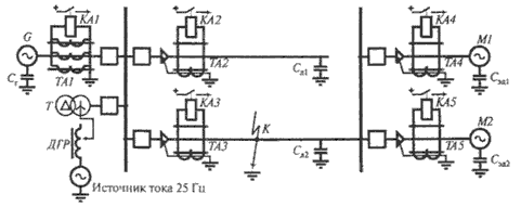
Figure 3. Security with "overlay" current
As a source of reference voltage is used electromagnetic parametric frequency divider. The output of the frequency divider winding in series with the primary winding of the ДРГ. When used in a network of ДРГ their yields from the land together and connected to earth ground through the output winding of the frequency divider. Protection of power lines is performed using special semiconductor filtrovyh current relay with an operating range at low frequencies that are connected to cable ТТНП
The difference in frequency of the unbalance current filter residual currents (50 Hz and harmonics of three) and the impact of the value (25 Hz) simplifies tuning–unbalance protection and avoids desensitization of protection to the primary current.
The disadvantages of these devices are the impact on the sustainability of the protection of error of zero sequence current transformer, increasing with decreasing the operating frequency, the circuit complexity of the primary switching because of the need to connect the power " overlay" current; difficulty connecting an auxiliary power source for use in a network of the ДРГ established on different objects, the complexity of the detuning from the natural harmonics at the outer arc of intermittent SPG, under which current spectrum depends on the network and its neutral ground; SPG position of the point in the network, and other factors.
2.5 Protection responsive to high–frequency components in the current zero–sequence occurring naturally.
Such protection can be divided into two classes of devices: an absolute measurement device (eg device type УСЗ–2/2 (personal device), microprocessor devices "Сириус", microprocessor devices SPAC 801–013, SPAC 801–113); devices and the relative measurement УСЗ–3М (served by hand and alternately connected to the current transformers of all connections section or busbar), signaling devices SPG such as КДЗС–2, automatic centralized unit of relative measurement of the levels of higher harmonics – ПАУК (uses the principle of parallel comparison of input signals) .
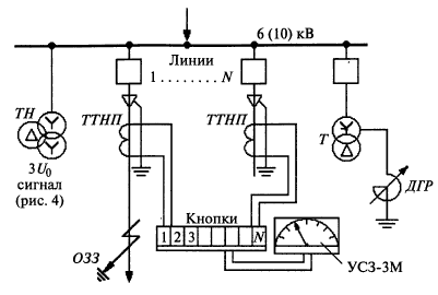
Figure 4. Circuit of the device УСЗ–3М. Toggle button without breaking the circuit.
Current absolute measurement devices are not effective in terms of volatility and the level of higher harmonics in the current zero–sequence that is especially true for networks 6 – 10 kV systems, electrosupply industry. The area of application of current centralized device relative measurement is much broader and mostly confined to errors cable ТТНП.
More than 30 years of experience with the УСЗ–3М, such as Lenenergo allows to praise this device, despite its known drawbacks: the unsuitability for use in complex networks with parallel lines, the inability to fix short–SPG, the need to exit the operating staff at the substation for of the large number of measurements in order to determine the faulty line and because of the time required for finding liyii with SPG.
3. Main content
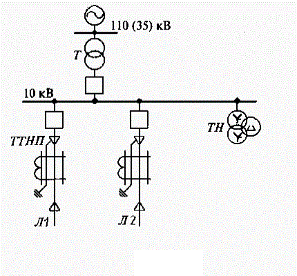
In Figure 5 shows a diagram of power supply section 3B of auxiliary systems for third block Zuyevskaya TES, which is made with respect to the mathematical model.
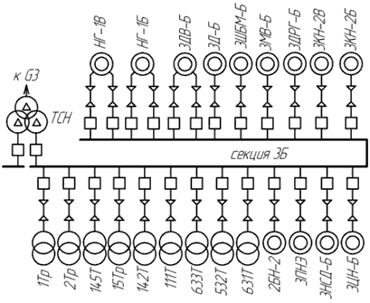
Figure 5. Schematic of auxiliary systems for power unit the third "Zuyevskaya TES"
Zuevskaya TES protection SPG works off the feeder with overcurrent SPG 3.2 A. Since the adoption of the single current setting operation of protection from SPG sensitivity of many feeders with significantly different capacitive currents own will not satisfy the requirements, the use of a single set point inappropriate. Therefore, the analysis of relay protection must be able to observe the transition process in each of the feeders. To do this, a mathematical model must consist of a system of differential equations of high order, which describes each feeder equivalent circuit.
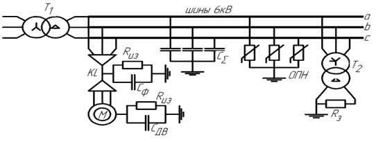
Figure 6. Design scheme of 6–10 kV power supply system s isolated neutral
Design model of the power supply system, which is composed by differential equations, is presented in Figure 6. It consists of a power transformer (T), the motor (M), which is connected to the feeding rails 6 kV with a cable (KL). Since the amount of current flowing through a single–phase ground fault only affects the capacity of the connection, the connection of the other substituted total capacity. Capacitance values of accessions were obtained during held at Zuevskaya TES experiment. To simulate the circuit on the tires in the scheme introduced by the insulation resistance Rиз. For the three–phase power supply is made equivalent circuit shown in Figure 7.
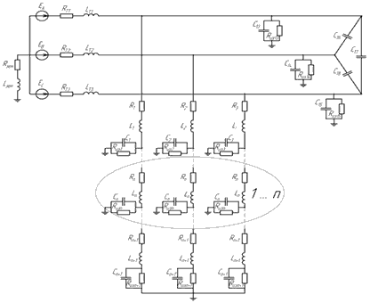
Figure 7. Three–phase equivalent circuit of auxiliary systems for eletrostantsii
In equivalent circuit into account the capacity between the phases of the network, as well as the possibility of grounding through the neutral resistive, inductive or capacitive reactance and install arresters directly on the output feeders. A ground fault can be simulated by zeroing the branch damage resistance at a given time (blind closure) and subsequent extinction of the arc resistance and the regeneration of said predetermined voltage insulation breakdown voltage recovery period.
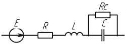
Figure 8. The equivalent circuit of the generalized branch network
The equivalent circuit includes a resistive and inductive impedance elements, as well as capacitance and insulation resistance network. Each branch is a generalized equivalent circuit branch (Figure 9) with a series–parallel connection of its R, L, C–elements which take account of the resistance element (R, L) and the insulation land (C, Rc).
To solve the resulting system of control is implicit discrete method for backward differentiation formulas (VOF), the basis of which, to allow for changing the pitch and calculation of the conversion is by formulas Gere. Differential equations for determining the instantaneous current and voltage at the branch capacity equivalent branches encoded by the formula Geer are of the form:


The advantage of this representation model for transient analysis is that the algorithm for calculating the steady–state and transient processes remains the same. The difference is that at each step of the calculation should update the transition resistance value and EMF branches. For the initial approximation for the calculation of the transition process are taken of the actual branch currents and voltages on vessels designed for pre–damage mode of operation of the network by the node voltages.
Since the nature of the transient process strongly influenced by nonlinear elements such as surge arresters and voltage transformers, the mathematical model takes into account their varying parameters at each step. For this purpose, use the characteristics of the arrester shown in Figure 10. Characteristics of OPN was obtained from the passport data and approximated OPN–KR/TEL–6/6.0UHL2 gradual dependence of the type 
where
 and
and
 – coefficients of the functions chosen analytically.
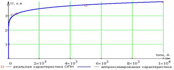
Figure 9 The nonlinear characteristic of the ОПН UОПН(IОПН)
On drawing up a mathematical model was developed program, through which performed an analysis of the transition process in the 6–10 kV networks with isolated neutral. Oscillograms of the phase voltages at break SPG the transition of power frequency current through 0 are shown in Figures 10–13.
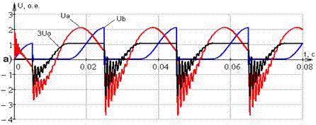
Figure 10. Waveform–phase voltages at break DOZZ the transition of power frequency current through 0
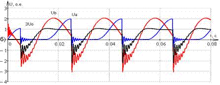
Figure 11. Waveform phase voltages when installing surge arresters
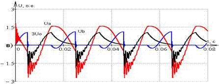
Figure 12. Waveform phase voltages when installing low voltage grounding resistor
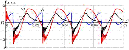
Figure 13. Waveform–phase voltages at the joint installation of low voltage surge arresters and grounding resistor
To test and determine the advantages of the developed mathematical model in the application of mathematical package MatLab Simulink was made visual model using the building blocks included in the library SimPowerSystems, which also allows the calculation of transients during short circuits. As a result, it was found that the algorithm, which is the basis of the model can significantly speed up the calculation of transients. A fragment of the visual model is shown in figure 14.
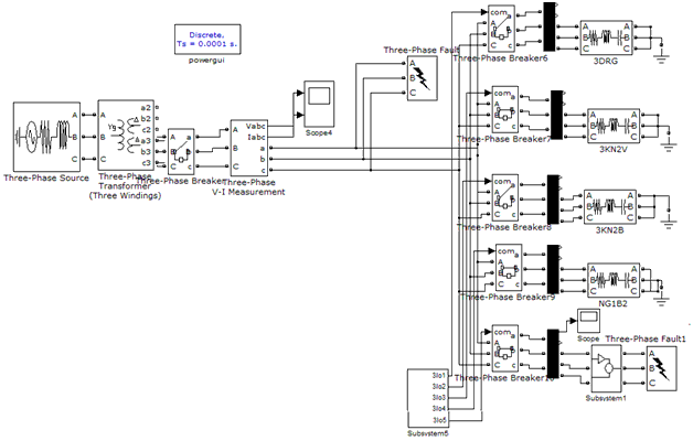
Figure 14. Detail of a mathematical model created in MatLab
Findings
A mathematical model of 6–10 kV network, which allows you to choose the most effective way to limit the surge arrester and check the thermal stability
In the simulation SPG found that the most effective way of earthing network is a joint installation of surge arresters and low–voltage neutral ground via a resistor, limiting surge to drop it 2.65Un.
In writing this essay master's work is not yet complete. Final completion: December 2013. Full text of the work and materials on the topic can be obtained from the author or his manager after that date.
References
- Шабад М. А., Защита от однофазных замыканий на землю в сетях 6 – 35 кB, Москва, НТФ "Энергопрогресс", "Энергетик", 2007
- Шалин А.И., Релейная защита от замыканий на землю в сетях с резистивным заземлением нейтрали, «ПНП БОЛИД», Новосибирск
- Шабад М. А. Защита и автоматика электрических сетей агропромышленных комплексов, Ленинград, Энергоатомиздат, 1987.
- Отчет о научно–исследовательской работе Г 09–323 ЗуТЭ. Сразработка и внедрение способов повышения чувствительности защиты от замыканий фазы на землю одной секции 6 кВ блока 300 МВт ЗуТЭС. 25.10.2010 г
- Правила устройства электроустановок. – М.: Энергоатомиздат, 1985, 640 с
- Противоаварийный циркуляр Главтехуправления Минэнерго СССР от 11.11.84 г. № Ц–11–84 "О повышении надежности собственных нужд 6 и 0,4 кВ энергоблоков"
- Циркуляр Ц–01–88 "О повышении надежности сетей 6 кВ собственных нужд энергоблоков АЭС"
- Циркуляр Ц–01–97(Э) "О повышении надежности сетей 6 кВ собственных нужд атомных станций".
- Отчет о научно–исследовательской работе Д–9–03 Развитие теории и методов ограничения перенапряжений в электрических системах при дуговых замыканиях фазы на землю20.12.2005 г
- Сивокобыленко В.Ф., Лебедев В.К., Махинда Сильва. Математическая модель для исследования переходных процессов при замыкании фазы на землю в сетях 6 – 10 кВ // Сб. научн. тр. ДонГТУ, Серия: Электротехника и энергетика, выпуск 4: – Донецк: ДонГТУ, 1999. – С. 221 – 226.