Abstract
Content
- Introduction
- 1. Actuality of the theme
- 2. Purpose and objectives of the work
- 3. Review of existing constructions of the drive motors
- 4. Analysis of the causes of malfunctions and engine failures
- 5. The main modes start of electric motors
- Conclusion
- References
Introduction
Improvement of technical and economic performance of the mining industry can be achieved through the use of advanced methods of mining, accelerate the pace of scientific and technological progress, improving the organization of production, improvement of process control systems and the industry as a whole.
The concentration of mining and widely used in the coal mines of high-performance mechanized cleaning and tunnel complexes leads to a significant increase pressures on transport links.
Significant traffic flows, deteriorating terms of coal mining and the complexity of the industry lead to continuous improvement of labor mining activities, including the underground transport [1].
Engineers and scientists achieved substantial progress in establishing a modern transport and excavation machines and scaling them in mines [2]. Meanwhile, some elements used cars in need of improvement.
The need to provide for mining enterprises powerful traffic associated with the concentration of mining activities, causes the development of the most advanced inline modes of transport, mainly conveyor, which opens great opportunities to increase capacity and reliability of its work, productivity and reduce production costs, as well as creating favorable conditions for complete automation of transport processes, improve safety and working conditions.
Pipelining transport in mines is mainly three types of conveyors: scraper, belt and plate, as well as some of their species and derived types. The choice of types of conveyors, their designs and options, as well as to establish the prospects for their use greatly influenced by the terms and conditions that apply to the operation of the conveyor transport them to the underground conditions of coal and ore mines, depending on the geological and mining factors.
Conveyor belts are now the primary means of continuous district and main transport in mines. Their widespread adoption is one of the most important factors in improving the efficiency and efficacy of mining [3].
The level of pipelining mining companies continuously growing, and the development of new large deposits will surely require the widespread introduction of more powerful conveyor belts and conveyor lines long distance [4].
The drive machinery used mainly electric alternating current machine, in particular, asynchronous motors. The dominant position of the number and the total installed capacity is occupied asynchronous motors with squirrel-cage rotor, characterized by simplicity of design and applied more often in unregulated drive. For smooth speed control using asynchronous squirrel-cage motors whose power is provided by thyristor converters or motors with slip-ring motors [5].
1. Actuality of the theme
Of alternating current motors most widely used induction motors due to their ease of device, and are used primarily three-phase electric motors. Three-phase asynchronous motors are the most mass-produced electric machine, but their reliability is insufficient.
The main reasons for failure are: improper maintenance, poor quality materials, a significant heat insulation, poor workmanship, high rate of rise of temperature of the windings in the emergency mode [6].
The sudden failure of the engine can lead to accidents and prolonged downtime of production, resulting in financial losses to be caused by a disruption of the process and the cost of restoration and repair of the motor.
In this regard, the question of improving the driving motors is important.
2. Purpose and objectives of the work
Purpose is to develop recommendations for improving the driving motors of conveyor installations.
To accomplish the above purpose the following main tasks:
- Perform review constructions of drive motors.
- Analyze the reasons for their malfunctions and failures.
- To consider the basic modes start of electric motors.
- Investigate the device and multi-speed motors offer their improvement.
3. Review of existing constructions of the drive motors
The conveyor refers to the mechanism of continuous operation with a constant distributed load.
Mode of operation of the motor in such a mechanism – long. When calculating its capacity, usually do not include the load at start-up and braking.
Many of the pipelines have enough hard drive train, contain elastic mechanical units, which affects the choice of the type of electric drive and control system because of the need for damping mechanical vibrations during start-up and braking.
Requirements to the drive belts:
- Speed control is not needed or required in a small range.
- Requiring higher starting torque due to the larger magnitude of the frictional torque at rest with respect to the friction torque movement.
- Necessary to ensure a smooth transition processes – limiting acceleration and jerk to avoid rocking or slipping mechanism and reduce the dynamic forces in the presence of elastic ties. It is advisable to start with the conveyor drive was characteristic with a gradual increase starting torque to start pulling away conveyor belt and the limited size of the time during ramp-up to full speed.
- If multiple drive rolls drive must provide a synchronization of the drive drum, i.e. establish the estimated distribution traction between the drive drums.
- Powerful drives high speed conveyor belt to provide a reduced rate of 1 m/s to conduct an inspection.
- Drive belts should provide a powerful reversal in local control.
Conveyors can be single-engine or multi-motor drive.
Multi-motor drives are used for the assembly lines of considerable length, even when the optimal location of the drive station on the highway does not provide relief to reduce the maximum allowable level, or when the technical and economic performance in multi-motor drive is better than the single engine.
Depending on the requirements for a smooth start and speed control in the mechanisms of distributed load applied:
- drives with squirrel cage induction motors with high starting torque;
- asynchronous motors with slip-ring motors for conveyor lines of great length to ensure a smooth start-up.
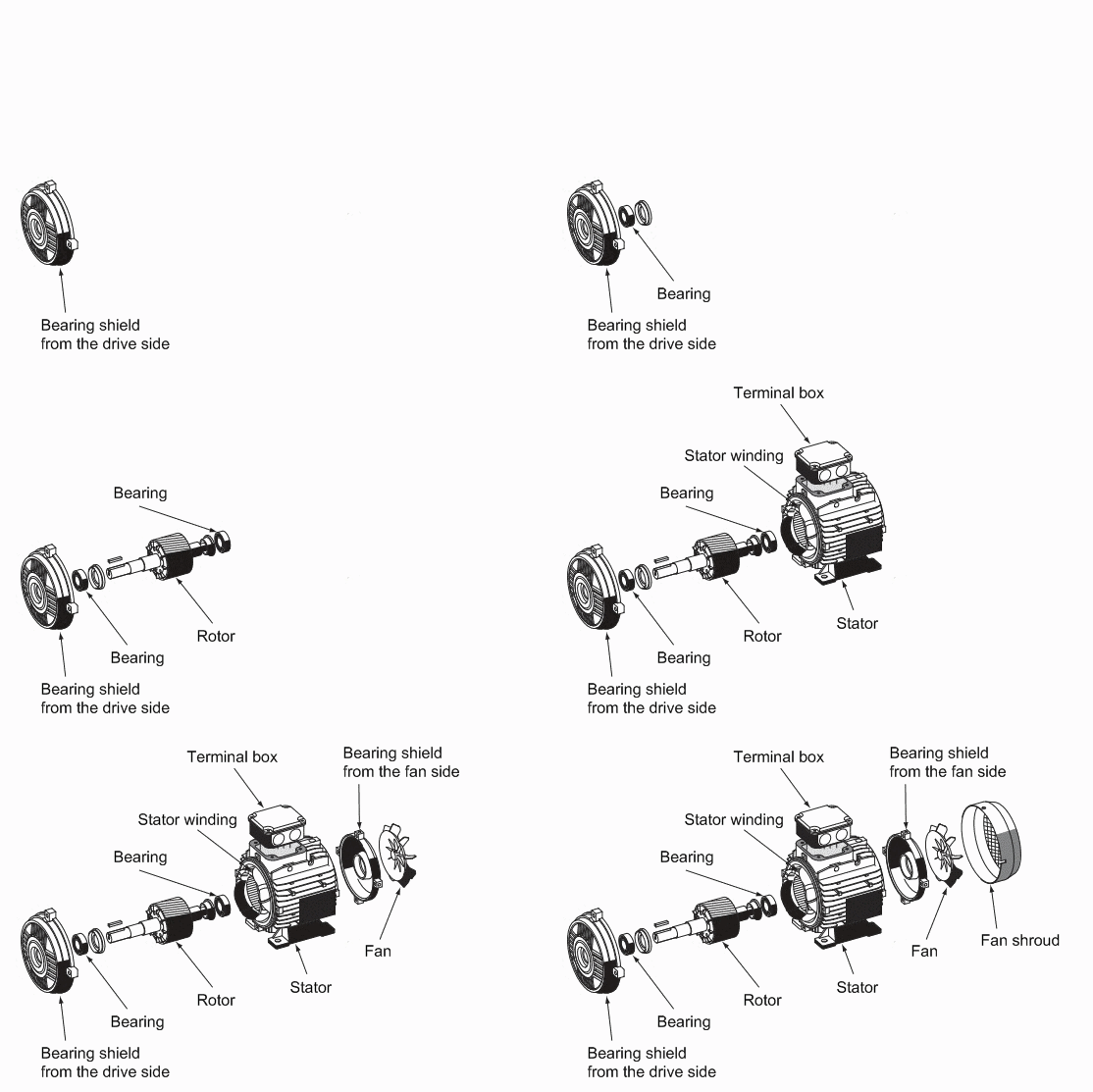
Figure 1 – Construction of squirrel cage induction motor
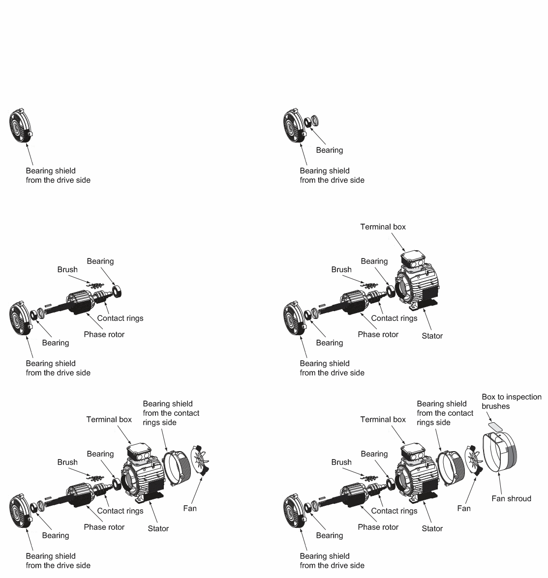
Figure 2 – Design of the engine with phase rotor
For drives that require speed control, the most promising electric scheme IF BP may also use the system AVC and DC electric scheme TC-M. Multi-motor drives in order to obtain a favorable load distribution between the engines used asynchronous squirrel-cage motors with high slip or asynchronous motors with slip-ring motors.
In the first case, improved load distribution between the motors due to a mild mechanical characteristics.
In the second case, the mechanical properties are aligned with the rotor included in the chain extension of an engine drag.
Moreover, the application of asynchronous motors with slip-ring motors solve the problem smooth start and starting current limitation with the potentiometric multi-stage start-up or a thyristor control current in the rotor.
Management of electric single conveyor, not associated with other mechanisms, produced by magnetic starters. Protection is carried out circuit breaker provides protection against overload and short circuit protection [7].
4. Analysis of the causes of malfunctions and engine failures
In electric motors, two types of faults: faults caused by the failure of the electric motor, and faults caused by external factors.
- Motor problems:
- single-phase ground fault;
- interphase short circuit;
- interturn short circuit;
- overheating of the windings;
- breaking the rod in the squirrel-cage motor;
- problem with the windings, etc.
- Malfunctions caused by external causes.
Their source is located outside of the motor, but the impact can damage the engine.
A failure may be caused by:
- The power source
- power off;
- wrong phase or phases of symmetry;
- voltage drop;
- overvoltage;
- other reasons.
- The working conditions of the engine
- overload;
- excessive number of starts or braking;
- violation of the start-up;
- too high moment of inertia of the load;
- other reasons.
- Improper installation of mechanical
- misalignment;
- imbalance;
- mechanical stress on the shaft;
- other reasons.
Faults in the engine
Fault stator or rotor
Stator winding of the motor consists of a copper wire insulated with varnish.
Violation of this isolation can cause permanent short circuit between phase and earth, between two or three phases or between the turns in one phase (Fig. 3). The root cause may be electrical (corona discharges, over-voltage), thermal (overheating) or mechanical (vibration, electromagnetic effects on the conductors).
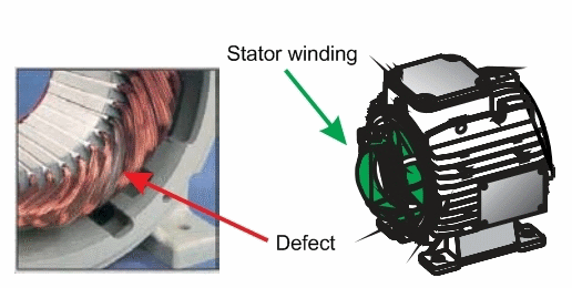
Figure 3 – Winding – is part of the engine, are most sensitive in damage the circuit and the denials of work
Insulation failure can also occur in the rotor winding with the same result – engine failure.
The most common cause of failure of the motor is overheating. Overloading causes an increase of power dissipation in the windings and their higher temperature.
The curve (Fig. 4), which provides the majority of manufacturers of electric motors, shows the dependence of the insulation resistance of the temperature: the temperature increases, the resistance of the insulation is reduced. In this case, service life of the windings and therefore the motor is significantly reduced.
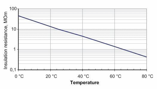
Figure 4 – The dependence on the temperature of the insulation resistance
The curve (Fig. 5) shows that the current increase of 5% equivalent of temperature increase of 10°, reduces the half service life the windings.
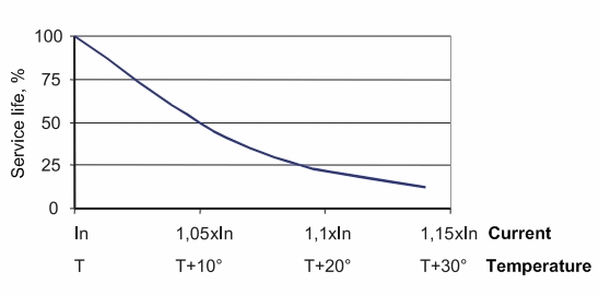
Figure 5 – The dependence of the lifetime of the overload and overheating
Therefore, to prevent overheating and reduce the risk of engine failure due to violations of the winding insulation must be protected from overload.
Malfunctions caused by external causes
Overvoltage
Any input voltage electrical equipment with a peak value exceeding the limits specified standard or specification is overexertion.
In temporary or permanent surge (Fig. 6) may have different origins:
- atmospheric (lightning);
- electrostatic discharges;
- work heat exchangers are connected to the same power source;
- other reasons.
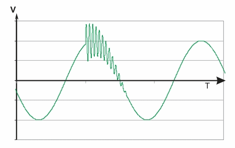
Figure 6 – Example overvoltages
Noise coming from the supply network can be of two types:
- common mode between the active conductor and the ground;
- differential treatment between active conductors.
In most cases strain leads to insulation breakdown of the motor, which outputs the electrical machine failure.
Unbalance
3-phase system is unbalanced when the three voltages are unequal amplitude and/or have a phase shift of 120° relative to each other.
The asymmetry (Fig. 7) can be caused by breakage phase single-phase loads in the vicinity, or by the power supply.
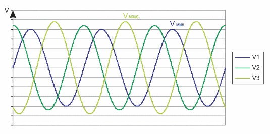
Figure 7 – The asymmetry of 3-phase voltage
The result of unbalance voltage is to increase the current required creating the desired torque, thus the engine is overheating.
Drop and voltage drop
The voltage drop (Fig. 8) – is a sudden drop in voltage in the power supply.
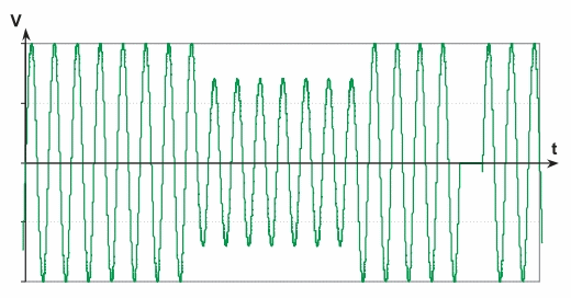
Figure 8 – An example of the voltage drop and short-term voltage dip
The voltage drop is seen in the range from 1 to 90% of rated voltage for a half cycle of 50 Hz for 1 ms to 10 min.
In accordance with the definition of short-term failure of the voltage drop in voltage is less than 90% of the nominal level of less than 3 minutes. If the voltage is not more than 3 minutes, it is considered a long brownouts.
Under mikropadeniem or mikroprovalom voltage means no voltage for about one millisecond.
The cause of the voltage can be as random external factors (a problem with the power supply or short circuit) and phenomena that are directly related to production (connection of large loads such as large motors or transformers). Effects caused by these factors can seriously affect the engine itself.
Harmonics
Harmonics can be harmful for AC motors.
Non-linear loads connected to the network, causing a non-sinusoidal current and voltage distortion.
Harmonics increase losses in the engines of eddy currents and cause further warming.
They can also cause increased torque pulsation (vibration, mechanical fatigue), noise pollution and limit the use of the engine at full load.
Faults engine associated with external causes
Engine start: too long and/or too often
Motor starting phase – the time required to reach the nominal speed.
With regard to the internal characteristics of the engine, it can support a limited number of starts, usually referred to by the manufacturer (number of starts per hour).
Also, the engine has a starting time, depending on the starting current (Fig. 9).
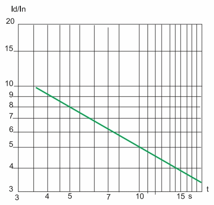
Figure 9 – Start-up time on the grounds of the inrush current to the rated current
Locked rotor
Engine seizure because of mechanical causes inrush current is approximately equal to the starting current. The result is a heating, which is much larger than in other cases because the losses in the rotor are the maximum for the duration of wedging in the absence of cooling of the engine, since it is usually associated with the motor rotation.
The rotor temperature can rise to 350°C.
Overload (small motor overload)
A small motor overload caused by increasing the moment of resistance or voltage drop (> 10% of rated voltage). Increased current consumption causes heating, which reduces the life of the engine and can be harmful to him with a short or long period of operation [8].
5. The main modes start of electric motors
- DOL;
- start switching from star to delta;
- start the engine using a portion of the windings;
- rheostat start with the resistance in the circuit of the stator;
- autotransformer;
- start the motor with slip rings;
- start/stop with soft starter;
- start using the drive.
In most real-world situations where we are upgrading an existing mechanism with the existing motor (asynchronous squirrel-cage motors and windings connected in star), conditional only two practical ways of "softening" of starting:
1) the starter (SCP);
2) frequency drive (inverter).
Start/stop with soft starter
It is an effective system to ensure a smooth start-up start and stop the engine.
It can be used to provide:
- motor current limit;
- torque control.
Changes in regulation of the torque optimizes torque during start-up and reduces the inrush current network. It is suitable for applications with constant torque loads.
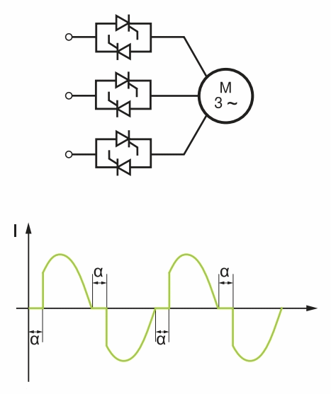
Figure 9 – The starter is an AC motor and its operating current
Benefits starter
The use of soft starters to reduce the inrush current, reducing the risk of overheating the engine, extending the life of the engine, remove jerks in the mechanical part of the drive at the time of starting and stopping the engine.
Along with the effect of the soft starter, soft starter can reduce active power consumption significantly reduce reactive power, to protect the engine, reduce noise, heat and vibration of the motor.
In turn, the starter (SCP) can not perform the following functions:
- adjust the speed of the engine at steady state;
- reverse the direction of rotation;
- to increase the rated torque;
- to reduce the inrush current to a value less than that required for the rotation of the rotor at the start.
Start with frequency converter
This is an effective launch system used to monitor and control the speed.
Can be used for the following applications:
- starting at loads with high inertia;
- starting with large loads with limited power source;
- optimization of energy consumption as a function of speed.
Start the system in question can be used for all types of machinery.
This solution is mainly used to control the motor speed, the launch is a side objective.
That is, frequency converters are used in conjunction with standard three-phase AC motors, in order to change the frequency of their rotation. Electric power is converted at the same time as follows [8]:

Figure 9 – The power supply circuit of the AC motor from the inverter
When starting the conveyor require starting torque equal to or somewhat greater than the rated torque of the motor. Therefore, the engine is started will depend on the conveyor and start everything associated with it consequences.
Conclusion
Induction motors are widely used in all fields of technology. This is especially true of simple in design and durable three-phase asynchronous motors with squirrel cage, which is cheaper and more reliable all-electric motors and require virtually no maintenance free.
Its simple design, high reliability and low cost of the asynchronous motor with squirrel cage rotor is the most common motor. Over 85% of all electric cars – this three-phase asynchronous motors.
The work is devoted to the improvement of the electric drive motors that by analyzing all of the above is relevant. At this stage the complete:
- Review of existing constructions of the drive motors.
- The causes malfunctions and engine failures.
- The basic modes start of electric motors.
It will be reviewed by the unit multi-speed motors and developed recommendations to improve them.
This master's work is not completed yet. Final completion: December 2013. The full text of the work and materials on the topic can be obtained from the author or his head after this date.
References
- Рудничный транспорт и подъем. Под общей редакцией профессора Н. Д. Мухопада. – Учебное пособие для студентов горных специальностей [Электронный ресурс]. – Режим доступа: http://donntu.ru/russian/strukt/kafedrs/wgzt_l/strMUHOPAD/book3.htm
- И. Г. Штокман, Л. И. Эппель. Прочность и долговечность тяговых органов. М., «Недра», 1967. 231 с.
- Шахмейстер Л. Г., Солод Г. И. Подземные конвейерные установки. Под ред. чл.-кор. АН СССР А. О. Спиваковского. М., «Недра», 1976. 432 с.
- Ленточные конвейеры в горной промышленности/В. А. Дьяков, Л. Г. Шахмейстер, В. Г. Дмитриев и др. Под ред. чл.-кор. АН СССР А. О. Спиваковского. М., «Недра», 1982. 349 с.
- Пархоменко А.И., Ширнин И.Г., Маслий А.К. Взрывозащищенные асинхронные электродвигатели: Справочник. – М: Недра, 1992. – 192 с.: ил.
- Асинхронные двигатели общего назначения/Бойко Е.П., Гаинцев Ю.В., Ковалев Ю.М. и др.; Под ред. В.М. Петрова и А.Э. Кравчика. – М.: Энергия, 1980. – 488 с., ил.
- EnergoVesta. Статьи. Электропривод конвейера [Электронный ресурс]. – Режим доступа: http://energo-vesta.com.ua/statiya/102-electroprivod-konveera.html
- Руководство по решениям автоматизации. Практические аспекты систем управления технологическими процессами/Schneider Electric S.A., Париж. – Редакторы перевода: Фролов Ю.А., Хохловский В.Н., ЗАО «Шнейдер Электрик», Москва.
