
Abstract

Ilya Truten
Faculty of Mechanical Engineering (FME)
Department of mining and factory transport and logistic
Speciality Lifting and Shifting, road, building, reclamation machines and equipment
Substantiation of the basic operational parameters and development intermediate actuator main conveyor belt
Scientific adviser: Ph.D., Associate Professor Victor Shavlak
Contents
- Introduction
- 1 Actuality of theme, goal and tasks of work
- 1.1 Actuality of theme
- 1.2 Goal and tasks of work
- 2 Review and analysis of the known constructions of intermediate drives of belt conveyers
- 3 Theoretical researches on the determination of the parameters and the installation of intermediate line drive belt conveyors
- 3.1 Description of the developed intermediate drive
- 3.2 Description of the algorithm of the program
- Conclusion
- References
Introduction
There is a trend in the world economy towards alternative sources of energy due to the exhaustion of oil and gas reserves. Ukraine is rich in coal and other minerals – the sources of alternative energy and global demand for them increases, so the mining industry is the dominant sector of the country with a promising future [1].
In the mining industry a significant role is for lifting-transport engineering, tasked wide implementation in all fields of management of complex mechanization and automation of production processes in basic and auxiliary operations, as a basis for improving the efficiency of production [2].
The most highly productive type of permanent machines is a belt conveyor. Belt conveyors are an integral part of industrial machines, as full or partial belt lining production ensures the intensity of reference works and increases the productivity of labor, regardless of the distance transport path [3].
The presence of intermediate drives in the main belt conveyors provide transportation without over-workings large extent, which contributes to more intensive production and reduces the workload on the cargo branch by spreading along the conveyor traction, which increases belt’s term of exploitation. Small intermediate drives are convenient for installation and repair. All of these factors promote further research and development of intermediate drives on the main conveyor belts [3].
This question is the main subject of this work.
1 Actuality of theme, goal and tasks of work
1.1 Actuality of theme
Questions about the research and development of intermediate drives main conveyor belt engaged scientists such as Ph.D. Kost G.N. [4], Polosuhin A.Y. [4], Ph.D. Kotov М.А. [4], Ph.D. Diachkov V.К. [5], Konovalov V.S. [6, 7, 8], Barishev А.I. [9], Prof. Budishevsky V.А. [9], Prof. Geyer V.G. [10], Prof. Shtockman I.G. [11], Spivakovsky А.О. [3], Dyakov V.А. [3].
Questions about the topic studied by such institutions and research organizations as DNTU [9 – 11], DonNUET them. Tugan-Baranovsky [9], VNIIPTMASH [4 – 8], IGD them. A.A. Skochinskiy [4], Dongiprouglemash [9].
Belt conveyors with intermediate drives produce such firms as: Steel Bone
(England) [9], Eriez
(USA) [9], Mitsubishi Denki
(Japan) [9], Inter
and <Salzgitter
(Germany) [9], Alexander Machine Plant
(Russia) [9].
The most highly productive machines are belt transport conveyors.
Belt conveyors are widely used in the coal industry, where full or partial pipelining of large mines provides intensive mining operations and increases productivity.
The level of pipelining mining companies is constantly growing, and the development of new large deposits will surely require the widespread introduction of more powerful conveyor belts and conveyor lines of greater extent.
At the present, more than 50% of the prime cost of coal is the cost of its transportation from the working face of the mine to the surface, making urgent search for reserves efficiency mine transportation devices, including belt conveyors.
Rational solution to the problem of increasing efficiency in the use of belt conveyors should be recognized installation on production machines intermediate drives (based on the research conducted by the GZTL Department of Donetsk National Technical University with the mine management Octyabrskoe
IA Donetskugol
[9]).
The presence of intermediate drives in the main belt conveyors provides unoverloading transportation to develop a large extent, which contributes to more intensive production and eliminates spray and crushing of the transported cargo, reduces the workload of the cargo branch by spreading along the conveyor traction, which increases belt’s term of exploitation. Small intermediate drives are convenient for installation and repair.
For a more rational and efficient use of belt conveyors further research is needed to optimize the design of existing and the development of entirely new types of intermediate drives.
Based on the above, the topic of this work is actual.
1.2 Goal and tasks of work
The goal of work is to choose the most efficient layout and the type of intermediate drives, depending on the design and operation of the main features of the conveyor belt.
To achieve this goal the following objectives:
- Check the main provisions of the earlier theoretical assumptions;
- Analysis of the known structures of intermediate drives and selects the best option;
- The calculation of load distribution between the drives when the load along the length of the conveyor;
- Distribution calculation driving force to the upper and lower branch of the conveyor;
- Determination of load-carrying belt tension depending on the distribution of driving force along the conveyor with the drive availability;
- Calculate the number of drives, depending on the required traction and power;
- Development of a design the optimal variant of the drive.
2 Review and analysis of the known constructions of intermediate drives of belt conveyers
In this section, we discuss the design features of various types of intermediate results not only massively used on conveyor belts at the moment, but experimental models of drives that have not been widely used in industry but are very promising for the future of their implementation.
The main advantage of using the drives is increasing the length of belt conveyors or performance without increasing the tension in the loop tape, as well as transportation by non-overloading workings large extent.
Intermediate friction drive
This type of conveyor drive leads to the movement through the force of friction occurring between the drive circuit and the main belt.
Belt conveyor with intermediate friction drive with a flat contact friction (Fig. 2.1). The conveyor consists of 1 load-bearing belt, 2 intermediate drives, 3 intermediate driving roll drives, 4 wheel drive load-carrying belt.
Tractive force is transmitted from the load-bearing belt drive belt loop due to the occurrence of friction between of them [3].
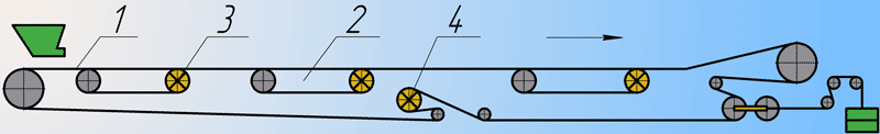
Fig. 2.1. Scheme of belt conveyor with intermediate friction drive
Under the leadership of Ph.D. Kotov M.A. with Ph.D. Kost G.N. and engineer Polosuhin A.J. in IGD them. A.A. Skochinskiy with VNIIPTMASH was built experimental model of Multi-drive conveyor of friction action.
The angle of the conveyor to the horizontal is 16°, the total length of 42 m, it was found two drive belt loop belt width 1000 mm, resulting in the movement of the load-carrying tape of the same width. The conveyor has a drive consisting of gear SKR-1 and short-motor type AO-73-4 capacity of 28 kW and speed – 1460 rev/min.
Multy-drive important parameter is the reference of the belt drive length of the contact strips and the load-bearing to the length of the conveyor. In this example, the change of this ratio is achieved by moving the drive belt under the roller load-carrying belt. The maximum length of one of the drive circuit is 13,5 m. Load-carrying and drive belts have five strips of belting B-820 [4].
Firms Krupp Industry
and Shtahlbau
(Germany) tested the intermediate friction drive belt-type conveyor belt on a high (capacity 16000 t/h) in the Rhenish lignite basin. Tests were started by setting a length of two drive belts 150 and 300 m, integrated between the upper and lower branches of the primary conveyor. However, due to the high coefficient of friction between the load bearing and drive belts of a conveyor length of 300 m was soon refused.
At present, a similar intermediate drive installed pas trunk conveyor belt length 1100 m, connecting the quarry with the CHP (Fig. 2.2).
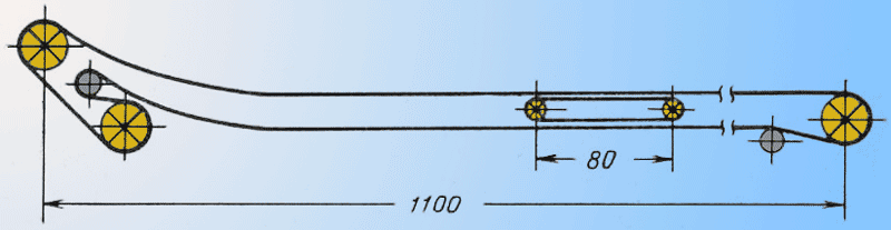
Fig. 2.2. Scheme of belt conveyor intermediate friction drive belt type
Conveyor-belt with two endless belts and intermediate drives (Fig. 2.3) is produced by english firm Cable Belt
.
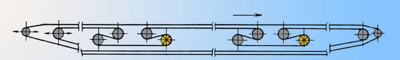
Fig. 2.3. Scheme of the two conveyor belt
One conveyor belt is a load-bearing, and the second — the traction. Actuators are located between the upper and lower branches of belts (Fig. 2.4). Apply induction motors with squirrel-cage rotor. Connection the motor shaft with shaft drive pulley is adjustable hydraulic clutch. When the tension exceeds a certain allowable limit for the drive, capstan 4 shift and compression of the spring 5 will reach a position that using a fluid coupling rod 8 of the blade will be derived from oil. Hydraulic clutch slip and increase the load redistribution is divided into other drives. During the period of steady pipeline control system automatically adjusts the boot drive in accordance with the loading area of the belt [12].
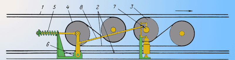
Fig. 2.4. Intermediate drive scheme:
1 – load-carrying tape; 2 – tape drive; 3 – drive pulley; 4 – capstan; 5 – the tension spring unit; 6 – axis of rotation; 7 – adjustable hydraulic clutch; 8 – traction
Magneto-frictional intermediate drive
In this type of traction drive transmission occurs by magnetic friction forces arising between the drive and the main belt.
Experimental model of magnetic friction intermediate drive (Fig. 2.5) manufactured in Donetsk Polytechnic University on the basis of ГШ-2. Drive station 1 comprises a motor, chain and two-stage clutch gear attached to the sidewall 2. Magnetic sections consist of a traverse of 3 and mounted them on the permanent cast horseshoe magnets 4. Girders strengthened to two infinite standard traction detachable chains.
The frame is situated on two supports 5, 6. Girders are made in such a way that when a belt-drive on its grooved shape is not changed. The magnetic system is located between the branches of the conveyor belt. Drive may interact with only one tape upper branch or both branches simultaneously. For this purpose, there are special rollers on the lower brunch of the belt guide.
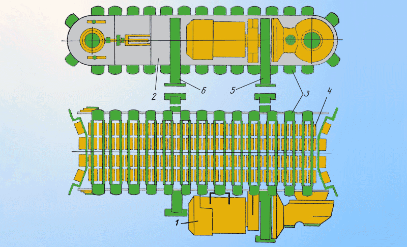
Fig. 2.5. Scheme of the experimental sample of magnetic friction intermediate drive
In a conveyor belt with magnetic friction intermediate drives as traction and load-bearing body may be applied a standard tape or a special soft magnetic tape which includes soft magnetic vehicle (ПЖ-3). The advantage of the first is that it is already commercially available, disadvantage – underutilization of its strength properties. More economically is to expedient to use the second type of belt.
Belt conveyor with frictional magnetic tape drive can be applied to a small number of spacers. This reduces the cost of tape on a setting [10, 11].
On the basis of experimental and scientific researches of Donetsk National Technical University and Dongiprouglemash in the Alexandrovsky machine-building plant (Russia) on the basis of commercially available the conveyor belt 1L-80 was manufactured a multi-drive magnetic belt conveyor MBC (Fig. 2.6).
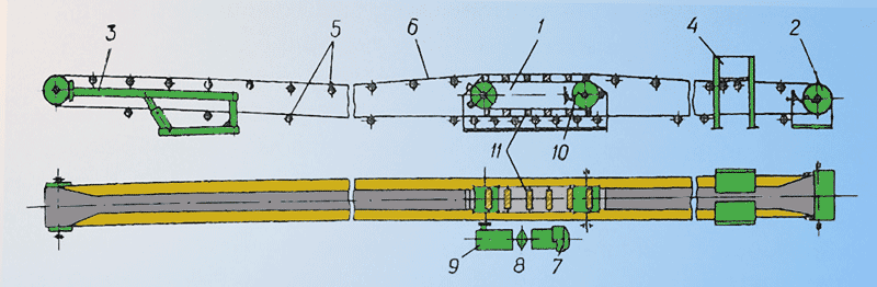
Fig. 2.6. Scheme of the multi-drive magnetic belt conveyor MBC
MBC conveyor consists of an intermediate magnetic – friction drive 1, tensioner 2, unloader 3, bypass drum feeder spring type 4, composition 5, tape 6. Intermediate drive unit is supplied with the drive unit which is consisting of an electric motor 7, turbo couplings 8, gear 9. The drive unit is mounted in cantilever fashion, which reduces the width of the marker.
For tighten the drive chain intermediate drive is used the screw device 10. Between the drive and tension sections are set а linear section. Their number depends on the length of the drive and the traction force exerted by it. To drive circuits are mounted magnetic blocks 11 and create a tractive effort which is transmitted to the tape. Units are installed at 300 mm, which according to research is the most optimal step. Magnetic blocks in one set on rollers that move on rails.
Blocks are (Fig. 2.7) consist of two magnet-carriers, a plastic box 1, which recruited magnets 3, alternating with the iron core 4. The magnets are oriented so that the poles facing one magnetic circuit, have the same name. For the magnetic system are used barium oxide-permanent magnets, which in comparison with cast magnets have a lower cost and provide more power but are afraid of mechanical bumps and temperature changes.
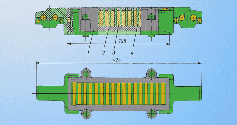
Fig. 2.7. Мagnetic block scheme
Pipeline Operation is as follows: intermediate drive shaft sprocket drive traction chains with moving magnetic blocks due to recent magnetic frictional contact movement is transmitted to the tape.
With the availability of intermediate drives redistribution of loads on the load-carrying belt and there is no need to use high-strength belt high value and complex tensioners, grind transported goods [9, 12].
The linear induction motor (LIM)
This type of actuator is distributed along the conveyor. The linear motor may be represented as a plane unfolded stator asynchronous squirrel-cage motor, the linear motor portion is fixed by winding disposed therein an alternating current, creating the alternating field.
Pipeline construction IGD Minchermet USSR with linear induction motors (Fig. 2.8) is equipped with the usual Conway ernoy band 2, which is attached to the support bracket 8, mounted on the suspension 7. Last mounted on wheel sets 6, moving on rails 9. At the end stations are non-driven drums 5 for the tape guides for the wheel sets are made in the form of a semicircle.
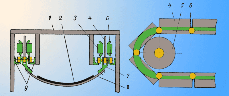
Fig. 2.8. Scheme conveyor belt with a linear induction motor
Each rotor 4 lined induction motor is consisted of hinged aluminum plates. Axis joints are both carrying axes wheel sets. On the frame 1 across the length of the conveyor stators 3 are mounted. The distance between them depend on the desired tractive effort. Tractive forces resulting from interaction of the magnetic (running) of the stator field dotted fields, induced in the plates of the rotor is transmitted to the entire system and traverse through each tape.
Induction intermediate drive
It combines the features of asynchronous motors, with a flat or arcuate stator and induction pumps and gutters for pumping liquid metals.
A scheme of one branch of the pipeline (Fig. 2.9) has a one-way drive with induction intermediate conductive non-ferromagnetic rotor part, hereinafter referred to as non-ferromagnetic rotor.
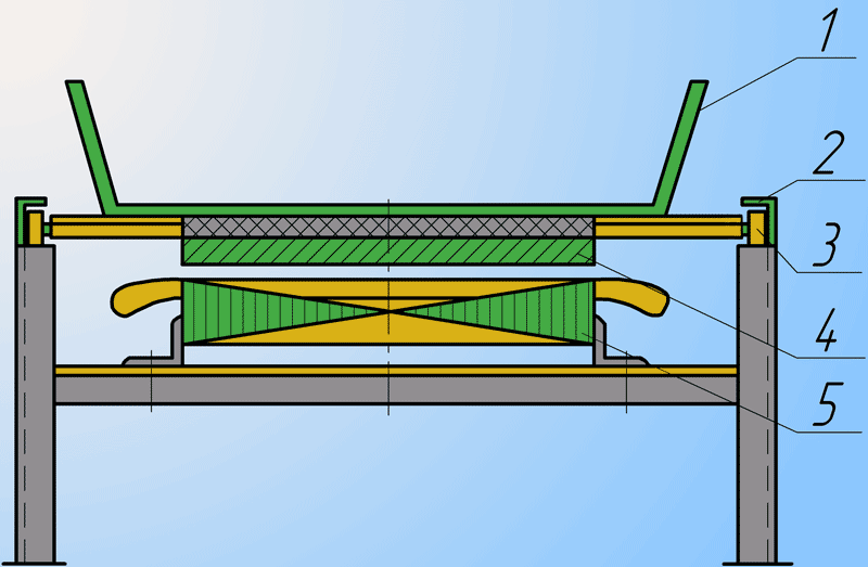
Fig. 2.9. Scheme of the unilateral induction drive with a non-ferromagnetic rotor
The carrier sheet 1 is moved along the guide rollers 2 to 3. In the lower portion of the carrier web is a solid or a squirrel cage type conductor (copper, aluminum or brass), the rotor 4. Inductor 5 creates a Traveling
magnetic field. The inductor consists of a core formed of an electrical steel sheets, and three-phase windings in the slots on the surface of the inductor. Traveling
magnetic field induces currents in the rotor, which interact with the magnetic field of the inductor, providing a driving force [10].
Bilateral induction drive (Fig. 2.10). Two blocks of flat inductors 5 are positioned vertically. In the gap there between is non-ferromagnetic rotor 4 attached to the carrier web [10].
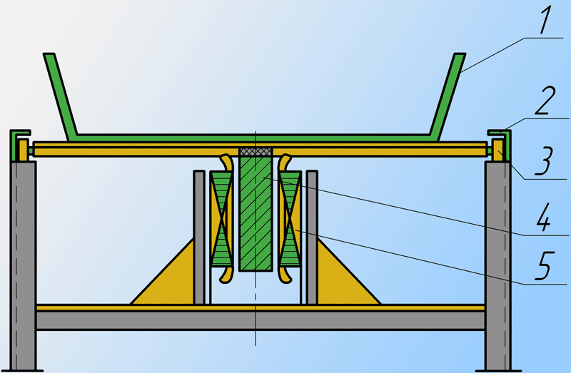
Fig. 2.10. Scheme of the bilateral induction drive
Unilateral induction drive with a ferromagnetic rotor (Fig. 2.11). Attached to the bottom of the section 4 packets of electrical steel, which are embedded in copper, aluminum or brass rods are closed at the ends of each circuit [10].
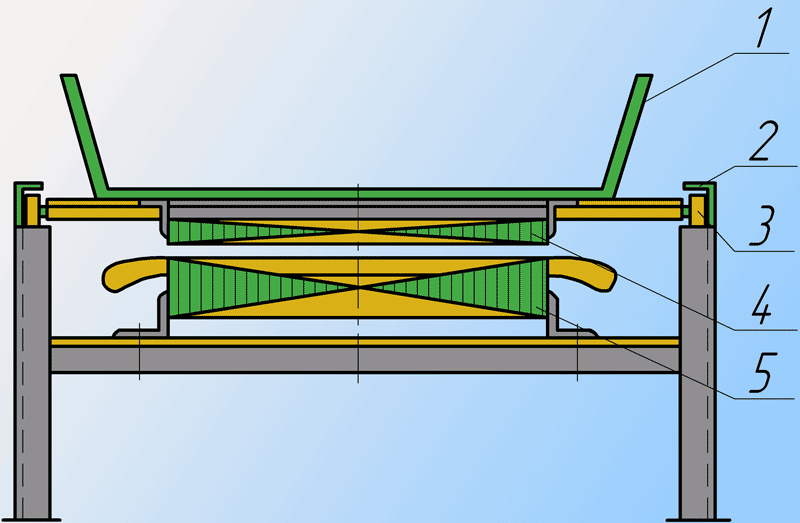
Fig. 2.11. Scheme of the unilateral induction drive with a ferromagnetic rotor
The greatest benefits of using structural induction drive with a one-sided non-ferromagnetic rotor. However, the open magnetic drive system creates a magnetic field in the rotor of low intensity. Reversible induction drive has significantly better compared to one-way, energy parameters, however it has a complicated structure. An intermediate position between these two types of drives is a one-way drive with induction ferromagnetic rotor. Ferromagnetic rotor closes the magnetic fluxes, greatly improving the energy performance of a unilateral drive [10].
Based on our review, with all the advantages and disadvantages of the considered structures of industrial drives, further work will be carried out towards the development of a drive with clutch booster, since the installation of this type of drive is the most efficient and cost-effective.
3 Theoretical researches on the determination of the parameters and the installation of intermediate line drive belt conveyors
3.1 Description of the developed intermediate drive
Developed intermediate drive consists of a closed loop drive belt that goes around the drive and tension drums. The interaction of the traction belt load bearing is between the upper branch of the drive and load or idle branch of the pipeline based on the location.
Fig. 3.1. Operation of the intermediate drive and tensioner
(animation: 5 frames, 7 cycles of repeating, 8 kilobytes)
The drive uses the traction tape EP series that have a small thickness and weight, but the tapes of this series are high performance desktop tension [13, 14].
To improve traction drive factor used magnetic blocks consisting of stationary magnets 2BA, 3BA [15, 16]. The use of magnetic blocks can reduce the length of the drive with the required traction by increasing the coupling between towing and load-carrying straps. The location blocks is between idlers conveyor so that their installation is the least influence on overall construction conveyor. The geometry of the magnetic system repeats the form of a grooved roller is achieved by selecting the required width of the units most appropriate roll width, and location of these units at an angle corresponding to the angle of the roller idler rollers. This allows the use of larger contact surface traction tape drive with the main band, increases the area of action of magnetic forces on the tape, prevent overlap the main strip, and on the cargo branch contributes to a better filling of the load tapes formed by the trough
3.2 Description of the algorithm of the program
For the analysis of the theoretical curves that define the possible layout of the intermediate drive along the conveyor, and the number of parameters under different conditions of transportation, a program calculation using high-level language programming VBA.
Input data required for analysis are available under the program interface (Fig. 3.2). Which has a button Вычисление
, Результаты
, Очистка
, Выход
with the help of which are managed by the program.

Fig. 3.2. Interface design program
To traverse the main parameters used in the program transport two cycles. The first cycle of the calculation is organized by sorting the possible angles of the conveyor β. As soon as the angle β is outside the permissible value, the calculation is performed in the second cycle (which changes hourly productivity conveyor Qt within Qmin – Qmax, with fixed step ΔQ, this cycle also includes the first.
The required number of drives selected from the condition required power generated by them.
Place the installation drive for both branches is chosen from the condition of full use of the strength of the tape. If the number of drives of the conditions required power exceeds the amount necessary to ensure the integrity of tape drives is to install the load-carrying arm with providing fixed pitch, which depends on the number of installed drives.
The calculation results are displayed on a sheet of Excel.
Conclusion
Conveyors with intermediate pretexts were established relatively recently. This explains the variety of proposed design solutions and the performance of most small conveyors. With the accumulation of data on the operation of such pipelines will be found the more perspective types of drives.
When taking into account all the above factors, the installation of intermediate drives on main conveyor belts are in demand and quite promising due to earlier research and innovation, but the issue requires a number of additional studies aimed at completion of existing deficiencies.
In this paper an attempt is made to combine the results of studies of previous years with a view to their complex processing by the computer to find the most rational design parameters of the intermediate drive and its location along the length of the conveyor belt.
In writing this essay master's work is not yet complete. Final completion: December 2013. Full text of the work and materials on the topic can be obtained from the author or his manager after that date.
References
- Украинские бизнес ресурсы [Электронный ресурс]. – Режим доступа: http://www.ubr.org.ua/page/2.
- Роль подъемно-транспортных машин в современном промышленном производстве. Классификация грузоподъемных машин, назначение, конструктивные особенности [Электронный ресурс]. – Режим доступа: http://www.dgma.donetsk.ua/metod/amm/ptm_lections.pdf.
- Ленточные конвейеры в горной промышленности/В. А. Дьяков, Л. Г. Шахмейстер, В. Г. Дмитриев и др. Под редакцией чл.-кор. АН СССР А. О. Спиваковского. М., Недра, 1982. 349 с.
- Исследование подвесных и многоприводных ленточных конвейеров, Выпуск 2 (89), под редакцией к. т. н. Дьячкова В. К., 1969.
- Дьячков В. К., Рождественская Л. А. исследование тяговой способности промежуточного привода многоприводного ленточного конвейера с фрикционной связью без дополнительных побудителей сцепления. Труды ВНИИПТМАШ, вып. 9 (62), Москва, 1965.
- Коновалов В. С. Перспективные типы машин для транспортирования массовых сыпучих грузов на средние и дальние расстояния. ОТИ, ВНИИПТМАШ, М., 1960.
- Коновалов В. С., Качанов В. Ф. Определение областей применения и основных параметров многоприводных ленточных и ленточно-канатных конвейеров для транспортирования массовых сыпучих грузов на дальние расстояния. ВНИИПТМАШ, НИ-4022-4023, М., 1963.
- Коновалов В. С., Качанов В. Ф. Технико-экономическое сравнение одноприводных и многоприводных ленточных конвейеров. ВНИИПТМАШ, НИ – 2168, 1966.
- Розрахунок і проектування транспортних засобів безперервної дії. О. І. Баришев, В. О. Будішевський, М. А. Скляров, А. О. Суліма, О. М. Ткачук. Навчальній посібник для ВНЗ. Під заг. ред. В. О. Будішевського. – Донецьк, 2005. – 689с.
- Начала магнитного транспорта, В. Г. Гейер, изд. «Недра», Москва, 1966.
- Основы создания магнитных транспортных установок. Штокман И. Г. М., изд-во «Недра», 1972, с. 192 (стр. 124-126).
- Васильев М. В., Волотковский В. С., Кармаев Г. Д. Конвейеры большой протяженности на открытых работах. М., «Недра», 1977. 248с.
- Транспортные ленты Trellex на тканевой основе [Электронный ресурс]. – Режим доступа: http://www.metso.com/Textile_Belts_RU.pdf.
- Конвейерные ленты [Электронный ресурс]. – Режим доступа: http://www.urrti.ru/lenti-konveiernie.html
- Постоянные магниты: Справочник/Альтман А. Б., П 63 Герберг А. Н., Гладышев П. А. и др.: Под ред. Ю. М. Пятина – 2-е изд., перераб. и доп. – М. Энергия, 1980. – 488 с., ил.
- Магнитотвердые ферриты [Электронный ресурс]. – Режим доступа: http://uas.su/books/newmaterial/244/razdel244.php