Abstract
Contents
- Introduction
- 1. Relevance of the topic
- 2. The purpose and objectives of the study
- 3. Scraper conveyor as an object of research
- 4. The research results
- 4.1 Technical capabilities of quasi frequency mode
- 4.2 Justification algorithm of switching the asynchronous engine from a quasi frequency mode on the nominal
- 4.3 Justification the principle of modeling the processes in system “quasi frequency converter – asynchronous engine”
- Conclusions
- References
Introduction
Scraper conveyors are the main transport devices for movement of mountain weight from a face and productivity of all mine depends on their reliability of work. Operation of the conveyor is characterized by existence of the raised moments of resistance. In some cases the cancelled start-up caused by a gumming of traction body take place. Use of the hydrocoupling doesn't allow to solve a problem of automatic wedging and protection of the electric drive against a gumming therefore scientific and practical relevance is represented by a problem to search and justification alternative ways of management by starting modes the electric drive of the scraper conveyor in the conditions the raised moments of resistance.
1. Relevance of the topic
Operation of the mine scraper conveyor differs intensive dispersal of traction body at start-up that creates danger the traumatism to the service personnel in the constrained space of a clearing face. Besides, start-up of the loaded scraper conveyor that is interfaced to need the overcoming a raised moments to resistance in use take place. By researches [1] it is proved that resistance moment at start-off of the scraper conveyor by 1,6-1,8 times exceeds the size of the moment resistance in the course of movement (fig. 1) [1].
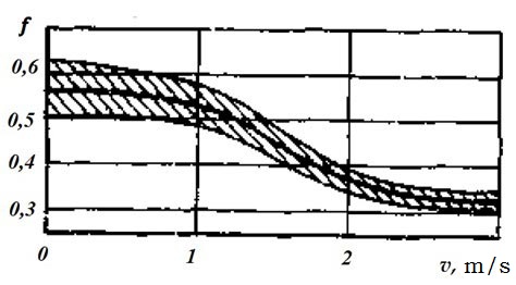
Figure 1 – Graph of the resistance to the movement the working body of the scraper conveyor from its speed
Today for ensuring smoothness of start-up the conveyor in its electric drive the hydrocoupling is provided. However its protective functions are realized not fully. The mechanical characteristic of the hydrocoupling allows to carry out dispersal at small loading of the asynchronous engine (AE), however creates conditions for sharp of surge the rotating moment on transmission at achievement by the engine of rated speed. The high moment inertia of the hydrocoupling leads to increase in stretching efforts of traction body when latching that promotes a chain rush [2].
These circumstances made it necessary to search a new technical solutions in the field of start-up mode the drive. The long-term level of the drive stage start speed should be proportional to the speed of movement a person in a stope and not exceed 0,2-0,3 m/s [2]. Based on these requirements, start-scraper conveyor can be realized by controlling the rotor speed of AE. Analysis of the known methods of frequency regulation suggests that the most suitable for these conditions is the way quasi frequency control of blood pressure, in which on the software group switching thyristor power switch at the output generated three-phase low voltage fixed frequency.
2. The purpose and objectives of the study
The purpose of the study is to improve the operational efficiency of coal mine scraper conveyor based on scientific substantiation of parameters and structure the device quasi frequency motor control with automatic translation engine on the natural mechanical characteristics.
The main objectives of the study are:
- Analytical review of research and development in the field AE start-up mine scraper conveyor.
- Development of mathematical and computer models of the “quasi frequency - asynchronous engine”, the study and analysis of the processes in it.
- Development of technical solutions to automate starting the scraper conveyor.
- Substantiation requirements for the safe operation of the developed automation tools.
3. Scraper conveyor as an object of research
The scraper conveyor is a continuous means of transport, traction body which is endless chain (one, two or three) with fixed thereto scrapers. When driving chain scrapers capture material conveyed and the trough to move it in the direction of the chain. Scraper conveyor device is shown in figure 2.
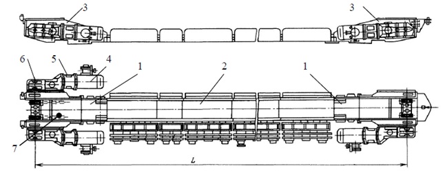
Figure 2 – Typical layout of the scraper conveyor for example SP-202M
Scraper conveyor may be have one or two motor 1 at one or both ends of panline 2. Each drive it contains one to two drive units 3. As part of the drive unit comprises in series a AE of cage 4, 5, and fluid coupling reducer 6. The main purpose is to ensure the smooth hydraulic clutch actuator assembly line start-up, as well as the protection of scraper chain 7 from the rush in the locking of [3].
4. The research results
4.1 Technical capabilities of quasi frequency mode
Quasi frequency mode power supply provides a stable blood pressure decreased and the rotor speed can be used to implement the low speed stage when the drive start. The subsequent dispersal to the rated speed of the rotor AE involves switching frequencies with reduced voltage to nominal.
Formation quasi frequency voltage by means of the modulation voltage frequency fc signal low frequency fm, by switching power thyristors groups thyristor switch at a given law.
Figure 3 shows the mechanical properties of blood pressure in quasi frequency mode, taking into account the rotation of the rotor EMF (frequency 10 Hz).
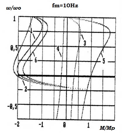
Figure 3 – Mechanical properties of blood pressure in quasi frequency management including EMF rotor
The resulting mechanical characteristic of AE 1 is the sum of the static characteristics, determined by the first, fifth, seventh, etc. harmonic voltages (curves 2, 3, 5). Comparing the resulting 1 and 5 natural mechanical characteristics of blood pressure can be seen when quasi frequency managing synchronous speed of the rotor corresponds to the simulation frequency voltage at this time blood pressure at start-up can be greatly increased [4].
Thus, the power supply mode quasi frequency AE provides:
- increased electromagnetic torque;
- stable lower speed of the rotor and can be used to implement a low-level speed of the drive at the start;
- the possibility of reversing contactor without switching.
4.2 Justification algorithm of switching the asynchronous engine from a quasi frequency mode on the nominal
Stepped switching AE with a rated quasi frequency mode associated with the effect of jerk, since there is a decrease in the rate of blood pressure caused by the mismatch between the vectors of linkages [5].
The task of suppressing shock moments in AE with its dispersal by increasing the frequency of the discrete voltage can be solved in the open-loop control systems, semiconductor converters due to software changes over time control actions applied to the input of the converter, and to ensure the inclusion directional further mode. In case of equal in magnitude and phase matching of vectors the initial and steady-state stator flux (rotor), the value of the transition moment in blood pressure is equal to zero [5]. This condition can be satisfied by a smooth variation of the frequency of the voltage supplied to the AE. To ensure that the motor torque AE network and the frequency ratio quasi-sinusoidal voltage is (3n ± 1), where n – the number of natural numbers. Thus, the ratio fc / fm = (6n ± 1) allows to achieve total symmetry in the form of quasi-sinusoidal phase voltage half-waves, and [6]. Obviously, it is advantageous to acceleration of blood pressure with a fixed frequency fm = 50 / 7 = 7,14 Гц.
The task of implementing managed dispersal of blood pressure should be solved by increasing the frequency of discrete quasi frequency stress on the principle of matching the phase vectors of current, voltage, flux linkage corresponding to the time of the end of the preceding and following the start time of the power mode of AE.
Given that the three phase voltages quasi frequency can be achieved as in fc / fm = (6n ± 1), and in fc / fm = (3n ± 1) appropriate to assume that the first stage engine acceleration managed should be translation from frequency 7,14 Hz to 12,5 Hz, accompanied by an increased frequency of group switching thyristor keys. Given that the open state of the thyristors in each group according to its duration would be contrary to the duration of the state groups thyristors at fc / fm = (3n±1), in this case, rational or even eliminate the inclusion groups of odd intervals thyristors set of relevant fc / fm = (6n ± 1). A similar approach may be used for the subsequent adaptation of the intermediate range spatial position of the motor flux vector mode power supply with a nominal voltage. In this case it is appropriate to increase the frequency of the voltage to 16,67 Hz (fc / fm = 3n) assuming that the frequency will be increased accordingly switching thyristor keys, and stresses in the form of a periodic phase thyristor controller will be provided by alternating states and included pauses between them. A sequence diagram for generating thyristor frequency 7,14 Hz, 12,5 Hz and 16,67 Hz is given in Table 1 [7].
Table 1 – The sequence diagram of thyristors
|
|
|
| |||||
|
|
|
|
|
|
| ||
|
|
|
|
|
|
|
|
|
|
|
|
|
|
|
|
| |
|
|
|
|
|
|
|
| |
|
|
|
|
|
|
|
| |
|
|
|
|
|
|
|
| |
|
|
|
|
|
|
|
| |
|
|
|
| |||||
|
|
|
|
|
|
|
| |
|
|
| ||||||
|
|
|
|
|
|
|
| |
|
|
| ||||||
|
|
|
|
|
|
|
| |
|
|
|
|
|
|
|
|
|
|
|
| ||||||
|
|
| ||||||
|
|
|
|
|
|
|
| |
|
|
| ||||||
|
|
|
||||||
Thus, the dispersal of the drive is performed by applying a voltage to the AE sequence of frequencies: fc / fm = 7; fc / fm = 4; fc / fm = 3; fc / fm = 1.
4.3 Justification the principle of modeling the processes in system “quasi frequency converter – asynchronous engine”
For research the processes in system “kvazichastotny converter - asynchronous engine” is offered structure of computer model (fig. 4) [8].
In this computer model three couples counter and parallel models of tiristor act as the quasi frequency converter (VS1-VS6) connected to three-phase network (AC Voltage Source-AC Voltage Source2), which phases are shifted relatively each other on 120°. The input of each tiristor control command into a block pulse generator Pulse Generator1-Pulse Generator6, in the sequence shown in table 1.
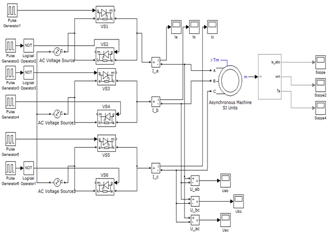
Figure 4 – The structure of a computer model "quasi frequency converter - asynchronous engine"
The resulting simulation sinusoidal voltages and currents shown in figures 5, 6 and 7.
Analyzing the figures 5 and 6, can be concluded that the impact of EMF rotation moment of switching thyristors move, which ultimately leads to increase current consumption (fig. 7).
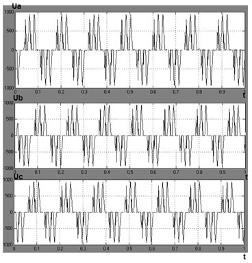
Figure 5 – Diagram quasi-sinusoidal voltages without affecting EMF of phase A, B, C respectively (fm = 7,14 Гц)
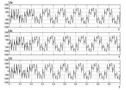
Figure 6 – Diagram quasi-sinusoidal voltages by the impact EMF of phase A, B, C respectively (fm = 7,14 Гц)
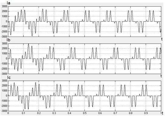
Figure 7 – Diagram quasi-sinusoidal currents of phase A, B, C respectively (fm = 7,14 Гц)
Conclusions
At justification of algorithm control the AE in the course of its transfer from a quasi frequency mode on the natural mechanical characteristic problem questions and ways of their decision are considered. On the basis of this algorithm developed a computer model system “quasi frequency converter – asynchronous engine” used to obtain quasi-sinusoidal diagram of voltages and currents at a frequency of 7,14 Hz quasi-sinusoidal stress and the effects of EMF AE.
The results obtained in the simulation of processes in the system “quasi frequency converter – asynchronous engine” allow to evaluate the functional properties of quasi frequency control AE.
References
- Чугреев Л.И. Динамика конвейеров с цепным тяговым органом / Л.И. Чугреев. – М.: Недра, 1976. – 256 с.
- Головатый М.В. Обоснование рациональности квазичастотного принципа управления приводом рудничной транспортной установки / М.В. Головатый, К.Н. Маренич // Материалы XI международной научно-технической студенческой конференции ДонНТУ «Механика жидкости и газа» 28-30 ноября 2012 г. – Донецк, 2012. – С. 16-18.
- Маренич К.Н. Автоматизований електропривод машин і установок шахт и рудників: навч. посібник для вузів / К.М. Маренич, Ю.В. Товстик, В.В. Турупалов, С.В. Василець, І.Я Лізан. – Донецьк: ДонНТУ, Харків: УІПА, 2011. – 245 с.
- Маренич К.Н. Асинхронный электропривод горных машин с тиристорными коммутаторами / К.М. Маренич. – Донецк: ДонДТУ, 1997. – 64 с.
- Трещев И.И. Методы исследования машин переменного тока / И.И. Трещев. – Л.: Энергия, 1969. – 235 с.
- Маренич К.Н. Асинхронный электропривод подземного скребкового конвейера с тиристорным пуско-защитным аппаратом / К.М. Маренич // Дис. канд. техн. наук. – Донецк, 1991. – С 54-56.
- Головатый М.В. Алгоритм управления асинхронным двигателем в процессе его перевода с квазичастотного режима на естественную механическую характеристику / М.В. Головатый, К.Н. Маренич // Cб. научных трудов. XIII научно-технической конференции аспирантов и студентов «Автоматизация технологических объектов и процессов. Поиск молодых» 14-17 мая 2013 г. – Донецк, 2013. – С. 116-118.
- Головатый М.В. Обоснование принципа моделирования процессов в системе «квазичастотный преобразователь – асинхронный двигатель» / М.В. Головатый, К.Н. Маренич // Cб. научных трудов. XII научно-технической конференции аспирантов и студентов «Автоматизация технологических объектов и процессов. Поиск молодых» 17-20 мая 2012 г. – Донецк, 2012. – С. 152-154.
- Лаусенко А.В. Скребковые конвейеры. Справочник / А.В. Леусенко. – М.: Недра, 1992. – 221 с.
- Штокман И.Г. Расчёт и конструирование горных транспортных машин и комплексов / И.Г. Штокман, П.М. Кондрахин, В.Н. Маценко. – М.: Недра, 1975. – 464 с.
- Петров Л.П. Тиристорные преобразователи напряжения для асинхронного электропривода / Л.П. Петров. – М.: Энергоатомиздат, 1986. – 200 с.
- Лазарев Ю. Моделирование процессов и систем в MATLAB / Ю. Лазарев. – СПб.: Питер, 2005. – 512 c.
- Герман-Галкин С.Г. Matlab & Simulink. Проектирование мехатронный систем на ПК / С.Г. Герман-Галкин – СПб.: КОРОНА-Век, 2008. – 368 с.
