
Abstract
Содержание
- Introduction
- 1. Theme actuality
- 2. Goal and tasks of research
- 3. Overview of researches and developments
- 3.1 General principles of code generation
- 3.2 Toolkit for implementation
- 4. IDEF0 concept
- 4.1 Model
- 4.2 Block modeling and graphical presentation
- 4.3 Precision and conciseness
- 4.4 Transfer information
- 4.5 Severity and formalism
- 4.6 Iterative modeling
- 5. IDEF0 semantics
- 5.1 The semantics of blocks and arrows
- 5.2 Names and labels
- 5.3 Semantic rules of blocks and arrows
- 5.4 IDEF0 diagrams
- 5.5 Context diagram of the top-level
- 5.6 Subsidiary chart
- 5.7 Parent chart
- 5.8 The text and glossary
- Conclusion
- References
Introduction
Permanent complication of the production and technical, organizational and economic systems - firms, enterprises, productions, and other of subjects of the production and technical activity - and the necessity of their analysis with the purpose of perfection of functioning and increase of efficiency is stipulated necessity of application of the special facilities of description and analysis of such systems. This problem acquires the special actuality in connection with appearance of computer-integrated computer-controlled productions and automated enterprises.
For the decision of problems methodology of Idef0 was chosen, features and receptions of application of which are described in this Leading document (LD), based on approach, developed Douglas T. Rossom at the beginning 70–ykh years and getting the name SADT (Structured Analysis & Design Technique is a method of structural analysis and planning)[6].
1. Theme actuality
Notation of Idef0 allows to design system functions (works, actions, operations, processes), functional connections and information (information and objects) which provide integration of system complexes. The developed models are valuable and associate description of activity of enterprise or functioning of the system[8].
In the total application of methodology of Idef0 follows will become the key for creation and modernization of software product.
2. Goal and tasks of research
The goal of work is development of software product which on the built diagram will destroy a programmatic code generation.
Basic research tasks:
- Analysis of different existent methodologies and languages of specifications for the decision of tasks about a programmatic code generation;
- Choice of methods of construction and use of specification on methodology of Idef0 for a code generation;
- Choice of algorithms which a source code will be generated on;
- Realization of applications in which components must be given for realization of programmatic code generation;
- Research of modern approaches for the improvement of applications.
Research object: the generation of source code.
Research subject: methods and algorithms used to construct the diagram.
3. Overview of researches and developments
The ideas of analysis of the systems, under which understand researches, beginnings from the general review of the system, are realized in Idef0, and then go into detail it as a hierarchical structure with the certain number of levels, on each of which no more than 8 elements. As a result the system is broken up on functional parts, their description is given, informative streams are probed and the structure of data is formalized.
3.1 General principles of code generation
Code generation - is a translation of the compiler internal representation of the source program in a string target language. A code generation generates a resulting object code in language of assembler or directly in absolute language (in absolute codes). The internal representation of the program may have any structure according to the compiler implementation, while the resultant program is always a linear sequence of commands. Therefore, generation of code (object code), it shall perform the actions associated with the transformation of complex syntactic structures in a linear chain.
Code generation can be considered as a function defined on the syntactic tree, which is built as a result of parsing. Ideally compiler to parse the entire input program, then to its semantic analysis, and then start to prepare the generation and 2 directly code generation [10].
A compiler executes a code generation stage-by-stage, on the basis of complete syntactic constructions of the entrance program. From text of the initial program a compiler selects a complete syntactic construction, also generates for it the fragment of code resulting and places it in text of the resulting program. Then he passes to the next syntactic construction So proceeds until all initial program will not be taken apart [11]. It is necessary to mark that the blocks of operators, descriptions of procedures and functions, come forward as analysable complete syntactic constructions. Their concrete composition depends on an input language and realization of compiler. Code of the almost prepared program, proper this syntactic construction executed depending on the type of syntactic construction generation. For semantically similar constructions different entrance PL can be created model resulting code.
3.2 Toolkit for implementation
A software product will have such structures of data, as unidimensional and two-dimensional arrays, lists, files, trees both other and base algorithms of maximum, minimum, sum, work, search of element, deletes etc. Every structure of data with the own variables will be on it unique. A decision to use the environment of development of Flashdevelop with the use of programming of Action Script 3.0 language that was accepted there were not conflicts with compatibility and logic of work was not violated. It is for this purpose necessary to use a few classes, each of which will be unique as well as structure of data with the set of variables. Every class will be is the structure of data. Also it touches base algorithms which will have the own classes.
Essence of programmatic code generation will consist of that at a cut-in program a superclass will cause necessary an user class with the certain structure of data, and then it will be required accordingly to choose a necessary algorithm.
For the decision of task it is necessary foremost to create Idef0 of diagram, and to connect them between itself.
After all aforesaid a code generation will pass stage-by-stage, and a file the generated programmatic code will be kept in which will be created as a result. On a Figure 1 Idef0 is shown diagram for an unidimensional array.
Figure 1 – Idef0 diagram for an unidimensional array
(x — input array, a — element, Res — index of founded element)
4. IDEF0 concept
Methodology of Idef0 is based on next conceptual positions.
4.1 Model
A model is an artificial object which is appearance of the system from its components. A model is developed for an analysis and making decision about processing of the system, to replacement existing, or creation of the absolutely new system. System – this is the aggregate of associate parts which co-operate with each other, and also execute certain work. A model describes that must take place in the system, management above it, what certain facilities the system must use for implementation of the functions.
4.2 Block modeling and graphical presentation
Functions – that is all, that takes place in the system and with its elements. Every function has a block. A block is a rectangle, and he can co-operate with other blocks or external environment by pointers. Pointers can enter or go out from a block. Pointers, which are included in a block show terms, which must be simultaneously executed in order that function, described a block executed the destiny.
4.3 Precision and conciseness
A document must be exact and compressed. A language must rotin very exactly and as far as possible briefly to rotin all elements of the system on a diagram, also connections and relations between them, and certainly to define superfluous or erroneous connections, if they are present.
4.4 Transfer information
Facilities of Idef0 facilitate an information transfer from one participant of development of model to other. Facilities:
- charts;
- natural language tags;
- serial decomposition diagrams;
- tree-like hierarchy diagram and block diagrams.
4.5 Severity and formalism
Here it is necessary to draw attention to the fact that all stages and phases of development should be strictly and formally documented. If all goes well, as required by the rules, then the likelihood of issues related to the incompleteness or inaccuracy of the documentation will be extremely small.
4.6 Iterative modeling
The model is developed step by step. The model is developed step by step. At each iteration step the developer offers the option of the model, which is subjected to discussion, peer review and editing, then the cycle repeats. This arrangement facilitates the optimal use of knowledge systems analyst familiar with the methodology and technique IDEF0, and knowledge of professionals - experts in the subject area to which the modeling object.
5. IDEF0 semantics
The table of contents of components of language is determined semantics which serves as support in the rightness of their interpretation. Accordance between blocks and pointers from one side and by functions and their interfaces – with other set interpretation.
5.1 The semantics of blocks and arrows
Name of block, which describes a function it must be in a verbal form. After the receipt of the name of block, to his certain sides it is needed to add the certain types of pointers. Arrows and their segments, refer to the form of the noun. Segment labels concretize the data or material objects that are passed to the segments in compliance with the syntax of mergers and splits.
The block, each party has its purpose in terms of the connection block / arrow. Each side of the block defines its role. If the needle is attached to the block on the left, it is an input. Inputs are transformed or consumed function to create what will be on her way out. If the needle unit is attached to the top, then it is running. Management primarily determine the conditions that are necessary for the function to Verne's output. If the arrow comes out of the block on the right, it is a day off. Outputs - this data or material objects that were set function. If the needle unit is attached to the bottom, it is the mechanism. If the arrow is pointing up, then it identifies the resources that support the work function [8]. If the downward arrow mechanism, it is a call to the arrow, and then it is referenced from this model (or model part) to the unit, which is part of another model (or another part of the model) and the support contact. Thus, different models or different of the same model can be used with one and the same element. Figure 2 shows views for example arrows.
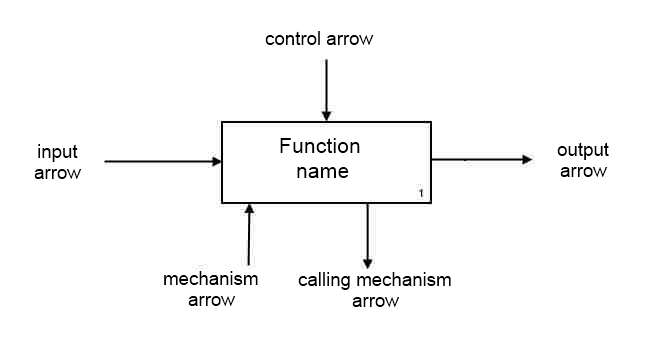
Figure 2 – Arrow types
5.2 Names and labels
Function names must be in verbal form. For instance: to process a request to block access to the database, delete. Each arrow must be named in the noun form. For example: loading, changing database, client name. Figure 3 shows an example of displaying the arrow mark.
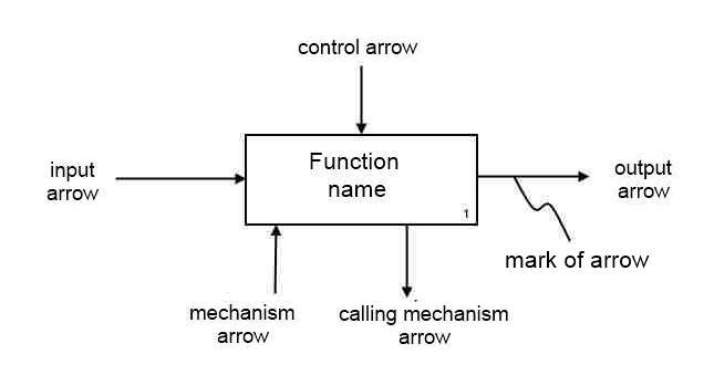
Figure 3 - Displaying the arrow mark
5.3 Semantic rules of blocks and arrows
The name of block must be in a verbal form.
Every side of block must have a standard relation of block/arrows:
- input arrows are connected to the left side of the block;
- the control arrow connected to the upper side of the block;
- output arrows attached to the right side of the block;
- mechanism arrows (except for arrow call) pointing upwards and connected to the bottom of the unit;
- arrows indicate the call mechanism down, attached to the underside of the unit and are referred to as reference to the calling block.
Segments of the shooter, except for the shooter Call named in the form of a noun, but only if the label does not apply to the arrow direction as a whole. For communication with the arrow mark, to represent "tilde" as shown in the example of Figure 4.
In arrow marks in any case you can not use terms such as:
- function;
- unput;
- ouput;
- control;
- мmechanism;
- call.
5.4 IDEF0 diagrams
There are 3 types of documents that are part of the IDEF0-model:
- graphic diagram;
- text;
- glossary.
Graphic diagram - is the main component of IDEF0-model, which contains the blocks, arrows, connecting blocks and arrows. Boxes indicate the function of the object [8]. These functions can be divided into parts and is presented in the form of detailed diagrams. As long as the object is described at the level of detail which is necessary to achieve the objectives of a specific project, the process of decomposition will continue.
5.5 Context diagram of the top-level
Each model must have a top-level context diagram, which is the object model shown in one block and arrows associated with it. This graph is called A-0. Arrows indicate the connection object to the environment. Chart A-0 sets the area of modeling and its border. Figure 4 shows a small example of what to look for A-0 diagram.
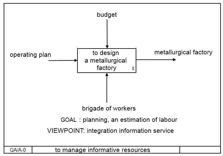
Figure 4 - A-0 diagram
Context A-0 diagram must also include a brief statement defining the point of view of an officer or unit to which the position is created model, and the purpose for which achievement of its developing. These statements help to guide the development of the model and put the process in a certain framework. Viewpoint determines what and in what context can be seen within the context model. Changing the viewpoint, leads to consideration of other aspects of an object. Aspects that are important from a point of view, may not appear in the model developed from a different point of view on the same object. Statement of purpose expresses the cause creating a model that is contains a list of questions that must meet a model that largely determines its structure.
5.6 Subsidiary chart
The sole function of which is represented by the top-level context diagram can be expanded to the main sub-functions by creating subsidiary diagram. Each sub-function can be decomposed into its constituent parts through the creation of a subsidiary of the chart at a lower level in which some or all functions may also be decomposed into its constituent parts. A subsidiary of the chart contains child nodes and arrows that provide additional detail parent unit[8].
5.7 Parent chart
Parental diagram - is a diagram which includes one or more parental blocks. Common chart can also be a child, as in it describes some parent unit. Any diagram can be both the parent and child, the unit can be obtained as the parent and child.
5.8 The text and glossary
The text used for the explanations and clarifications characteristics interblock connections and so forth, but the text does not need to be used to describe blocks and arrows, that's obvious.
As glossary it defines concepts and terms that must be understood by all participating users and develop models to to interpret its content.
Conclusion
Within the framework of this abstract on the topic of master's degree work general principles were exposed code generations which give to understand as a mechanism of code generation works on the whole, and review of conception and semantics of methodology of Idef0, which a diagram will be built by. So or differently the variant of the use of technology of XML of document is possible, as said in [7], which it will be easy for development code generators in a software product.
This master's work is not completed yet. Final completion: December 2013. The full text of the work and materials on the topic can be obtained from the author or his head after this date.
References
- IE 880I – Enterprise Engineering- Fall 2000 / IMfgE at Wichita State University / Paper #1 – IDEF Modeling / Swapnil Shah
- Журнал Qualitative Theory of Dynamical Systems / Выпуск №11, — 2012
- Gregor Kempery and Allan Steel // In: P. Draxler, G.O. Michler, C. M. Ringel, eds., Proceedings of the Euroconference on Computational Methods for Representations of Groups and Algebras, Progress in Mathematics, Birkhauser, Basel, 1998 (to appear)
- Канжелев С. Ю. Автоматическая генерация кода программ с явным выделением состояний, Software Engineering Conference (Russia) — 2006 (SEC (R) 2006), с. 60–63.
- International Journal of Business and Management / Chania, Greece - May, 2008
- Ross, D.: "Doug Ross Talks about Structured Analysis", IEEE Computer, July 1985
- The Server Side - Your j2ee community / Soumen Sarkar & Craig Cleveland Page 1 of 20 Code generation using XML based document
- О.А. Бистерфельд: МЕТОДОЛОГИЯ ФУНКЦИОНАЛЬНОГО МОДЕЛИРОВАНИЯ IDEF0, Учебно-методическое пособие / Рязань - 2008
- Кручинин А. Н. Автоматическая генерация программных компонент по высокоуровневым спецификациям, Ростов–на–Дону, 2006.
- Aхо А., Ульман Дж. Теория синтаксического анализа, перевода и компиляции. Том 1. Синтаксический анализ. – М.: Мир, 1978. – 613 с.
- Ахо А.В., Лам М. С., Сети Р., Ульман Дж. Д. Компиляторы: принципы, технологии и инструментарий, 2-е изд.: Пер. с англ. – М.: ООО Изд. дом Вильямс, 2008. – 1184 с.