
Abstract
While writing this abstract the master's work is not yet complete. The final completion - January 2014. Full text of the materials can be obtained from the author or his manager after that date.
Сontent
- Introduction
- 1. Purpose and tasks of study, planned results
- 2. Description of process equipment of air conditioning system
- 3. Application of chilling machines for air conditioning units
- 3.1 Compression chilling machines
- 3.2 Ejector chilling machines
- 3.3 Absorption chilling machines
- Techno-economic analysis of chilling machines
- Conclusions
- References
Introduction
Main task of energy engineering is establishment of required level of power supply that is reached not only with gross energy generation but also with energy conservation. In recent time, the alternative energy subject has become popular due to consistent rising of prices for organic fuels due to their exhaustibility, аs well as enhanced growth of energy consumption.
Main sources of alternative energy are:
- small rivers energy;
- tidal and ebb-tidal energy;
- solar energy;
- wind energy;
- geothermal energy;
- energy of combustible waste and emissions;
- energy of secondary or waste heat sources, and others.
Great attention is paid to enhancement of energy efficiency at the enterprises with the aid of secondary energy sources (SES).
In the industry, the amount of consumption of all generated thermal energy makes about 55%. Here, the efficiency of thermal energy at the enterprises does reach nearly 35%. Greatest amount of energy is just lost without recovery, namely: removed with flue gases emitted into the atmosphere, cooling water or heated products.
Secondary energy sources are the total energy potential of products being made, side and intermediate occurrences of that products, normalized and excess waste that appear during production process in process units, and which can’t be used in unit itself but may become source of supply for other energy consumers. SESs are split into following types:
- thermal;
- combustible;
- SES of excess head.
Thermal SES – heat of exhaust gases at combustion of fuel, heat of water or air , used for cooling of process facilities and units, water steam and condensate, and also other waste heat in production, for example, hot smelt slags.
Use of thermal SES is one of most perspective directions of alternative energy engineering development because it has significant effect on reduction of energy consumption of the company at low capital and operation costs.
1. Purpose and tasks of study, planned results
The study covers systems of ventilation and cooling of air in electrical rooms (HP, DP), and also in office and domestic premises of the industrial enterprise.
Purpose of study is development of process and engineering solutions, computations and selection of process equipment to maintain required parameters of air in the premises for safe and stable operation of electrical equipment accommodated in premises, at high temperatures of outdoor air , and also provision of optimum heat and moisture comfortable conditions in public access buildings premises.
Under result of performance of study there shall be planned definition of thermal and humidity loads, material and heat balances per every premise, refrigeration efficiency of air cooling in whole, and its individual elements.
2. Description of process equipment of air conditioning system
As source of cold required for processes of cooling and drying of air in conditioning units, usually various types of cooling machines are applied. Two principles of use of cooling machines for the purpose of air conditioning may be selected:
- with intermediate coolant, which is water cooled to the temperature 5-7 °С; water is fed with pumps to heat- and mass transfer devices in air conditioning system units and, after taking of heat from the air is returned to recooling in cooler heat exchangers;
- with direct boiling of refrigerant in heat exchangers integrated with central conditioners, or in channeled air coolers.
The first principle is mostly used in cold supply system from which the simultaneous supply with cold water to several facilities of air conditioning is performed. Such principle is called chiller-fancoil.
Chiller is a chilling machine designed for chilling of liquid heat carrier (water, antifreeze). Chilled liquid is fed via pipelines with aid of pump station to convector heat exchangers, accommodated in cooled premises. Such heat exchangers are called fancoil..
Fancoils may be considered as trip conditioners that can automatically switch on and switch off, and change their cold production efficiency. Heat exchanger - with aluminum fins attached to copper tube coils via which the cold water is fed.
Circulation of liquid from chiller to cold water consumer is provided with pump station which is integral unit that includes circulation pumps, extension tank, closing valves, and necessary instrument system. Pump station may be operated independently or be controlled by chiller. Normally, pump station operates complete with chiller and соntains required elements for adjustment with chiller and electrical elements for control.
3. Application of chilling machines for air conditioning units
Selection of type of chilling machine for cold supply system is determined with engineering and economical comparison of several variants subject to specific conditions of application: availability of SES, cost of electrical power, cooling water, duration of operation of air conditioning units, cost of equipment and refrigerant and other conditions.
3.1 Compression chilling machines.
Chillers on the basis of steam compression chilling machines are widely used in conditioning units for heat and moist treatment of air stream. Air is chilled in special-purpose evaporating heat exchangers where the refrigerant being boiled in tubes does actively absorb the heat from external air flow to finned surface of tubes. Continuous circulation of refrigerant in chilling cycle is provided with compressor that sucks vaporous refrigerant, that comes from evaporator, compresses and sends at high pressure to condenser for liquefaction.
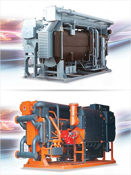
For extra large capacity chilling units, centrifuge (turbocompressor) chilling machines shall be considered. As an example, can be taking machines series 10ТХМВ-2000-2 (10ТХМВ-2000-2Т). Machine are designed for chilling of water and liquid coolant at large units of commercial and comfort air conditioning.
3.2 Ejector chilling machines.
Steam-water ejector chilling machines (SWCM) relate to main types of chilling heat-used machines. Ejector machines have found wide application in energy engineering (HES, SDPS, APP), providing chilled water to air conditioning system of premises of block boards of stations control, and also for process needs. To operate the SWCM, water steam with higher gage pressure 0,7-0,8 MPа and temperature about 250 °С are required. Compressor function (suction of refrigerant vаpors from evaporator and rise of their pressure to pressure in condenser) is performed with ejectors.
Compared with absorption bromic-lithium machines, the SWCM is characterized with lowered thermal factor f=(0,25-0,30 against 0,67-0,7), consumption of cooling water is 3-3.5 times higher than the same for absorption machines.
Despite lower specific quantity of metal of SWCM, сost of cold generation by them is higher than the same for ACM 3 times and more. In view of the above, the ПЭХМ are rejected from further review.
3.3 Absorption chilling machines.
As opposed to compression chilling machines, in the АCМ the circular process is performed with work mix of the media, which in most cases includes two components. These media have significantly different boiling temperatures at the same pressure. On component is refrigerant, and other one is absorbent. Compression of refrigerant vаpor from suction pressure to the high pressure of condensation is performed by thermochemical compressor which is set of vessels where the heat mass exchange occurs.
АCМ distinct in periodic and continuous action. In the industry, only continuous АCМ are used and further on, only this type of chilling machines will be discussed. As absorbents, solid and liquid media are used.
Solutions applied in АCМ can be divided, per type of refrigerant, into following group: water, ammonia, spirituous, freon, and hydrocarbon. Group of solutions where as a refrigerant water is used, include: H2O-LiBr, H2O-LiCl, H2O-LiJ, H2O-NaOH, Н2O-СаСl2, H2O-LiCl-LiBr. Mostly widely used of the solutions listed before is work mix H2O-LiBr, аnd for production of cold water in air conditioning systems in commercial scopes bromic-lithium chilling machines are mainly used, that allow using or recovery low-temperature potential heat.
Diagram of absorption bromic-lithium chilling machine with single-stage recovery of solution and with steam heating, is shown is an example on Figure 1.
Principle of machine action is based on the bromic lithium solution ability to absorb more cold water vapors. Cooled water comes into tube side of evaporator 1, where it is cooling to the required temperature due to evaporation in vacuum the refrigerant - water that flows in form of film in the tube side of evaporator. Water steams from evaporator come into tube side of absorber 2 where they are absorbed with aquatic solution of bromic lithium that flows in form of film. Heat emitted by absorption is rejected with chilling water which circulates in tubes of absorber. Solved (weak) solution from absorber is fed via heat exchanger 5 with pump 11 into tube side of generator 3 where it is evaporating due to external source of heat of heating steam that comes into tube side of generator. Weak solution via heat exchanger and solution ejector 6 returns to absorber. The steam that is forming in generator comes into condenser 4 where it is condensed, and condensate flows into evaporator.
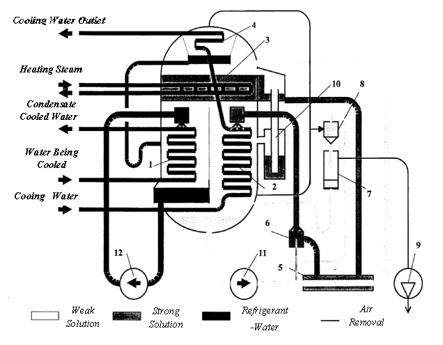
Figure 1. – Diagram of absorption bromic-lithium chilling machine with single-stage recovery of solution and with steam heating
In the diagram the are following conventions:
- Evaporator
- Absorber
- Generator
- Condenser
- Heat Exchanger
- Solution Ejector
- Gas Collector
- Vacuum Ejector
- Vacuum Pump
- Overflow Hydroseal
- Pump
- Pump
Inert non-condensing gases (air) are periodically removed from machine with vacuum pump 9 via degasser that consists of gas collector 7 and vacuum ejector 8. Overflow hydroseal 10 is provided for emergency overflow of solution from generator in case of its overfill, into absorber.
4. Techno-economic analysis of chilling machines
There was conducted engineering and economical analysis of application of chilling machines series ТХМВ, 4МКТ-350-2-1, АБХМ-3000, results are given in Table 1.
| The results of the feasibility analysis application of different types of chilling machines | |||
| Description | Type of chilling machine | ||
| АБХМ-3000 | ТХМВ | 4МКТ-350-2-1 | |
| Total Demand in Cold, kW | 3000 | ||
| Chilling Capacity in Equipment Unit, kW | 3000 | 3000 | 750 |
| Consumed Electrical Power Duty, kW | 23 | 650 | 185 |
| Hot Water Consumption (Condensate of SES) per one machine, t/h | 160 | - | - |
| Recycle Water Consumption (per one machine), м3/h | 650 | 600 | 130 |
| Amount of Refrigerant/Type, kg | 4500/LiBr | 1500/R-134а | 450/R-22 |
| Amount of Oil, kg | - | 150 | 120 |
Conclusions
In this case, use of АБХМ-3000 as compared with compression machines series ТХМВ and 4МКТ-350-2-1 enables reduction of initial capital costs approximately by 15%, аnd consume during operation process 2..2,5 times less resources because of use of heat of SES, that finally provides 20…30% less self-cost of cold generated by АБХМ rather that in case of use of compression machines.
References
- Автоматизация систем вентиляции и кондиционирования воздуха: Учебное пособие. Е.С. Бондарь, А.С. Гордиенко, В.А. Михайлов, Г.В. Нимич. Под общей ред. Е.С. Бондаря - К.: ТОВ "Видавничий будинок "Аванпост-Прим"2005.-560с.:ил.-Библиогр.:с.548-549.
- Ананьев В.А. и др. «Системы вентиляции и кондиционирования. Теория и практика».Учебное пособие. М.: «Евроклимат», изд-во «Арина», 2000, 416 с.
- Аэродинамика воздушных потоков в помещении. Шепелев И.А.:М.,Стройиздат, 1978.144с.
- Батурин В.В. Основы промышленной вентиляции. М., Профиздат, 1965.
- Богословский В.Н. Строительная теплофизика. М., Высшая школа, 1970.
- Зельдович Я.Б. Предельные законы свободно-восходящих конвективных потоков. - "ЖЭТФ".
- Каменев П.Н. Отопление и вентиляция. М., Стройиздат, 1996.
- Нимич Г.В. «Современные системы вентиляции и кондиционирования воздуха:Учеб.пособие/ Г.В. Нимич, В.А. Михайлов, Е.С. Бондарь.К.: ТОВ «Видавничий будинок «Аванпост Прим» 2003. 630с.: ил. Библиогр.: с. 625-627.
- Еремкин А.И., Королева Т.И. Тепловой режим зданий: Учебное пособие. М.: Издательство АСВ, 2000.
- Табунщиков Ю.А., Бродач М.М., Шилкин Н.В. Энергоэффективные здания. – М.: АВОК – ПРЕСС, 2003.
- Нестеренко А.В. Основы термодинамических расчетов вентиляции и кондиционирования воздуха. – М.: Высшая школа, 1971
- Баркалов Б.В., Карпис Е.Е. Кондиционирование воздуха в промышленных, общественных и жилых зданиях. – М.: Стройиздат, 1982.
- Кузьмин М.С., Овчинников П.А. Вытяжные и воздухораспределительные устройства. - М.: Стройиздат, 1987.
- Гримитлин М.И. Распределение воздуха в помещениях. - Санкт-Петербург, 1994.
- Кокорин О.Я. Современные системы кондиционирования воздуха. – М.: Издательство физико-математической литературы. 2003.
- Рымкевич А.А. Системный анализ оптимизации общеобменной вентиляции и кондициони- рования воздуха.-Санкт-Петербург, Издательство «АВОК СЕВЕРО-ЗАПАД», 2003.
- Тертичник Е.И. Вентиляция. – М.: Издательство АСВ, 2004.
- Справочник проектировщика. Вентиляция и кондиционирование воздуха/Под ред. И. Г. Староверова. М., Стройиздат, 1977.
- Справочник по специальным работам. Наладка, регулировка и эксплуатация систем промышленной вентиляции. М., Стройиздат, 1962.
- Попов В. П. Вентиляция и кондиционирование воздуха. Л ВИКА им. А. Ф. Можайского, 1972.