Abstract of master's work: "Study of electromagnetic visibility of objects, which are in the structure of the antenna system"
Сontent
- Introduction
- 1. Goal and tasks of research
- 2. The relevance of the topic
- 3. Alleged scientific novelty
- 4. Reducing the visibility of military equipment, and facilities
- 4.1 Radio-absorbing materials
- 5 Metamaterial
- 5.1 «Right» and «Left» the isotropic environment
- 6. Antenna ball
- 6.1 Radio transparent protective cap
- 6.2 Modernization
- Source list
Introduction
Currently urgent problem is the masking of radio systems. Although, for a long time and is widely used mimicry way to mask подсмотренный in insects and some representatives of flora, where the insects are impersonating twigs and leaves etc. In our world, the world of high technology, this method is great for masking antennas, for the same cellular, when, for example, issued for cacti, trees etc. There are more complex and expensive and qualitative methods visually disguise antenna, and they really work well. Given current technologies, detect, even with the help of high-quality optical devices, any well camouflaged complex with 100 meters indeed extremely difficult. But, unfortunately, the invisible antenna is still antenna and search, direction finding systems, aimed at the search of our complex still looks like antenna, not because they have no eyes, but because they «see» they are totally different. Now this is the main difficulty masking of antennas and radio systems. One of the standard methods of disguise is the use of protective cap (optically opaque screen), it is rather simple way, but unfortunately not very convenient in use. Offers a way to create radio opaque environment immediately around the antenna cap will Radio transparent. Advantages of this method is that there is no need to remove any equipment, just change internal filling under the hood, what would the antenna is working, or was invisible to the means of detection. One of the advantages of this method is that it can be applied to already existing antennas and complexes without making any changes in their design. At present the Department REIP Donetsk national technical University being developed to build a device capable of protecting the antenna from the search of radio-electronic means, without limiting its functionality, and speed regime change "operation", "invisibility".
1. Goal and tasks of research
The purpose of master's degree work is development of model of masking complex using radio opaque environment directly around the antenna, which will considerably reduce the effective size of the spill (EPR), and thus will make the whole complex barely visible for detection of radio-electronic means of intelligence.
To achieve this goal in master's degree work, you must perform the following tasks:
- Study of the methods of radio disguise.
- Comparative analysis of properties of electrolytic substances, and on its basis to choose meets our conditions mixture.
- Modeling of the antenna.
- Calculation of parameters of the antenna on the results of simulation.
- Modeling of the antenna with the use of camouflage.
- Calculation of parameters of the antenna on the results of the modeling with the use of camouflage.
- Experimental confirmation of the received data.
2. The relevance of the topic
Attempts to solve the problems of creation of the equipment and objects invisible radio equipment, have been made since the beginning of the development of radio razvedka. In this regard, the notion of the radio disguise. (Radio disguise - a complex of technical and organizational measures aimed at reducing the effectiveness of radio reconnaissance of the enemy). There are many ways to disguise by reducing the EDA by means of using various materials or structures in the composition of the antennas. The method of creating радионепрозрачной environment immediately around the antenna will upgrade the existing complexes without much interference in the design of antennas.
Thus, the issue of protection of antenna systems by reducing the EPR from the detection of radio-electronic means through the application of electrolytic substances remains topical at the moment.
3. Alleged scientific novelty
Development of model of masking equipment, which allows you to create radio opaque environment around the antenna Novo itself. The way to mask can be applied to the existing antennas after a small upgrade. Currently analogues system masking using electrolytes does not exist.
4. Reducing the visibility of military equipment, and facilities
Make objects invisible to the REFs extremely difficult. Perhaps only a few reduce the possibility of their detection intelligence RES, if the cover materials-absorbing EMW, and apply малоотражающие form. However, tangible results in reducing the range can be achieved only in case of sharp decrease of EPR objects. So, reduction of the EDA 16 times reduces the range radar detection of the object and just 2 times. [7. 102-103]
4.1 Radio-absorbing materials
Radio-absorbing materials are non-metallic materials, providing at the interaction with electromagnetic waves absorption, scattering and interference of their energy. On the principle of divide them into the gradient and interference.
5. Metamaterial
Metamaterials are artificial materials engineered to have properties that may not be found in nature. They are assemblies of multiple individual elements fashioned from conventional microscopic materials such as metals or plastics, but the materials are usually arranged in periodic patterns. Metamaterials gain their properties not from their composition, but from their exactingly-designed structures. Their precise shape, geometry, size, orientation and arrangement can affect the waves of light or sound in an unconventional manner, creating material properties which are unachievable with conventional materials. These metamaterials achieve desired effects by incorporating structural elements of sub-wavelength sizes, i.e. features that are actually smaller than the wavelength of the waves they affect.
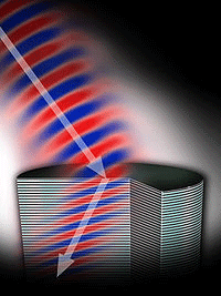
One of the possible properties of metamaterials - negative (or left) refractive index, which is shown while simultaneously negative permittivity and permeability. An example of such a metamaterial is shown in the Figure. [illustration 1. 10]
The equation of propagation of electromagnetic waves in an isotropic medium is:
k^2-(w/c)^2 n^2=0
k — the wave vector,
w — the frequency of the wave,
с — speed of light,
n^2=εμ — squared refractive index. From these equations, it is clear that a simultaneous change of the signs of ε dielectric and IX of the magnetic susceptibility of the medium does not affect these relations.
5.1 "Right" and "Left" the isotropic environment
Equation is derived from Maxwell's theory. For environments in which the dielectric e and the magnetic μ susceptibility of the environment at the same time positive, three vector of the electromagnetic field - electric E magnetic H and wave k form a system of so-called right-wing vectors: [kE]=(w/c)μH, [kH]=(w/c)εE.
Such environment, respectively, referred to as "right".
Environment, for which ε,μ — simultaneously negative, called "left". In such environments electric E, magnetic H and the wave vector k are left vectors.
In English literature described materials called right - and left-handed materials, or abbreviated RHM (right) and LHM (left), respectively.
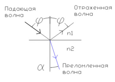 illustration 2.
Passage of light through the border environments, both of whose refractive index is positive n1>0,n2>0 [illustration 2. 10]
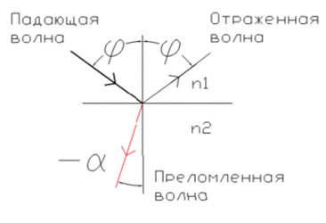 illustration 3.
Passage of light through the border environments, one of whom is the index of refraction is positive n1>0, and the other is negative n2<0 [illustration 3. 10]
The flow of energy transferred wave is determined by the Poynting vector S, which is equal to S=(c/4π)[EH] . Vector S always forms the vectors E, H right three. Thus, for right-handed substances S and k are in the same direction, and for left - different. Because the vector k coincides with the direction of the phase velocity, it is clear that the left substances are substances with a so-called negative phase velocity. In other words, the left-handed substances phase velocity is opposite to the flow of energy. For such substances, for example, there is a convert to the Doppler effect.
6. Antenna ball
illustration 4.
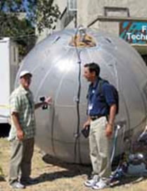
Ball antenna representing a conductors, inflicted by the method of film technology on the surface of the ball is filled with light gas, United with amplifying block, located in the lower part of the ball, the output of which is connected to the cable-cable, characterized in that the conductors are made in the form of annular framework with geometric parameters corresponding to the primary and secondary frequency bands, in which, through a half-wave periods included short-circuited quarter-wave transmission lines, combining adjacent frame, and to the waves of horizontal polarization of the frame are placed on Parallels the globe, and to the waves of the vertical polarization on his meridians. [illustration 4. 10]
6.1 Radio with protective cap
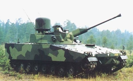 illustration 5.
On the roof of the tower under radio transparent dome mounted antenna radar detection and tracking of targets TRS-2620 "Герфаут" of the French firm "tomcoh"-csf. Radar-Doppler, millimeter wave, all-round view. [illustration 5. 10] Detection range up to 14 000 m
6.2 Modernization
• Proposed modernization of technology masking antennas.
• In this complex includes a device for creating radio opaque environment under the radio transparent dome.
• The essence of the method lies in the fact that under tight cap is blown gaseous metal (mercury vapor), thus under the hood is created radio opaque environment that hides the antenna.
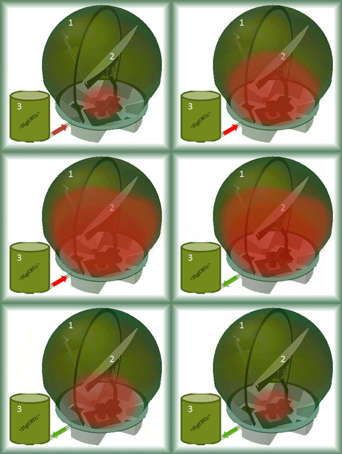
1 —Radio with protective cap.
2 — antenna.
3 — The unit discharge the right atmosphere
Illustration 6.
[Illustration 6] of change of internal filling under the hood (animation7 frames, repeat 7, 167kb)
Source list
- Антенны УКВ /Под ред. Г.З. Айзенберга. В 2-х ч. Ч. 2. - М.: Связь, 1977. - 288с. с ил.
- Антенны: (Современное состояние и проблемы)/ Под ред. чл.-корр. АН СССР Л.Д. Бахраха и проф. Д.И. Воскресенского.- М.: Сов. Радио, 1979.-208с
- Антенно-фидерные устройства и распространение радиоволн: Учебник для вузов/ Г.А. Ерохин, О.В. Чернышев и др.; Под ред. Г.А. Ерохина. – 3-е изд., - М.: Горячая линия-Телеком,2007.-491с.: ил.
- Жук М.С., Молочков Ю.Б. Антенно-фидерные устройства. М.: Энергия, 1966.
- Бекетов В.И. Антенны сверхвысоких частот: М.: Военное издательство министерства обороны союза ССР, 1957.
- Марков Г.Т., Сазонов Д.М. Антенны: Учебник для студентов радиотехнических специальностей вузов. 2-е изд., перераб. И доп. М.: Энергия, 1975.
- Палий А.И. Радиоэлектронная борьба. - 2-е
изд., перераб. и доп. - М.: Воениздат, 1989. - 350с., ил
- Ротхаммель К. Антенны: Пер. с нем. – 3-е изд., доп. – М.: Энергия, 1979. – 320 с., ил.
- Ротхаммель К., Кришке А. Антенны. Том 2: Пер. с нем. – Мн.: ОМО «Наш город», 2001. -416с.: ил.
- http://ru.wikipedia.org/wiki/ Электронный ресурс.
