


Abstract
Content
- Introduction
- 1. Calibration of photocameras
- 2. Calibration of cellphone’s camera on the calibration range
- Conclusion
- Sources
Introduction
Liberal pricing in the world market of mobile devices and their multifunctionality made cellphones as polulat devices among the general polulation. However, cellphones, which were designed for residental using originally, can be applied and in another activities.
Modern cellphine with digital camera allows not only to get the colorful high-quality image, but easy transfer image files to computer or another mobile devices via wireless oк cable connections. It gives the possibility to propose to use the mobile images as the source for measurement of captured objects by the remote method. Although need to understand, that the ideal optical system which is free from any an abberation is not exist. In the non-measurement cameras, the aberration’s values might be reach to the significal level. To minimize these aberations calibration might be aplied.
Now the issue of calibration of digital cameras is under valuable attentions, there are big amount of publications, which is devoted for this theme. Different approaches for calibration of small-format cameras are proposed by the authors, although these approaches are justified in economical terms and physically feasible, especially when the matter is camera of cellphone. Besides, now is not known is the cellphone’s cameras applicable for measurements.
This master’s work is devoted to the research of the possibility and practical applying of such procedures for measurements and checking for this aim the cameras of several available popular cellphones.To do this need to define the elements of image’s orienation – having these results the conclusion about the application cellphones for measurement can be accepted.
Object of study is camera of cellphones, subject of study is distortion of the optical system of cellphone’s camera.
Camera’s calibration will be executed with calibration range.
1. Calibration of photocameras
A camera consists of a image plane and a lens which provides a transformation between object space and image space. This transformation cannot be described perfectly by a perspective transformation because of distortions which occur between points on the object and the location of the images of those points. These distortions can be modelled. However, the model may only be an approximation to the real relationship. How closely the model conforms to reality will depend on the model and how well the model’s parameters can be estimated. Choosing parameters which are both necessary and sufficient has taxed those involved in the process of lens calibration for as long as lenses have been used to make precise measurements.
In recent years lens calibration has received less attention than in the period from 1950-1970. This may be attributed to the maturity of understanding of aerial lenses which in the past provided much of the stimulus for the development of models and calibration methods. Also, the widespread use of self calibration using bundle adjustment methods has meant that a high level of performance has become Common place. It may be argued that the current static situation means that there is no further research necessary. However, the development of camera calibration methods and models has always been interspersed with periods of relative stability. The demand for high-speed continuous measurement using large sensors arrays may require new advances to be made.
Notwithstanding any changes of terminology, the formulae proposed by Brown [11]. back in the 1960’s appears to have remain virtually unchallenged for the past 30 years. Brown’s formulations for radial and decentering distortion and for additional parameters in the bundle adjustment are described in terms of polynomials. Ziemann [15] (1986) notes that “polynomials ... are undesirable from a mathematical point of view because of the high correlation between the different terms. It is therefore necessary to agree not only on the formulations for the lens distortion components but also on the procedure used to solve for these parameters”. Ziemann proposed an algorithm for the step-by-step calibration of cameras so that the results from various calibrating authorities could be more easily compared, but it is doubted if his efforts were heeded. He suggested the order of calibration should be: the determination of rotationally-symmetric distortion; the calculation of an equivalent focal length; the determination of the decentering distortion with respect to the principal point of autocollimation; the determination of a point of best symmetry; the determination of the actual rotationally-symmetric lens distortion; and, simultaneous verification of both lens distortion components. More recently Shortis [16] (1995) has suggested the use of the plumbline technique to determine estimates for the parameters of radial and decentering distortion, and then the use of a multi-station convergent bundle adjustment to determine the focal length and offsets of the principal point while holding the previously determined parameters of lens distortion ‘fixed’. This procedure should be iterated with a re-calculation of the plumbline once the offsets of the principal point are known. This iterative, and relatively time consuming, procedure can overcome difficulties of correlation amongst parameters which might occur if the geometric strength of a self-calibration photogrammetric network is weak. If the network is strong, the need for procedures such as those described Shortis may not be necessary as a satisfactory solution to the camera and lens parameters can be obtained from the bundle adjustment.
2. Calibration of cellphone’s camera on the calibration range
The calibration range is the set of points with 3d-coordinates. Becouse of variation of Z-coordinates is not significall, this range is classified as flat range. This range is fixed on the wall of 2.399 lecture’s auditory of Department of geodesy and geoinformatics. Schematically the range and his coordnate’s system re presented in the pic. 2.1 [9].
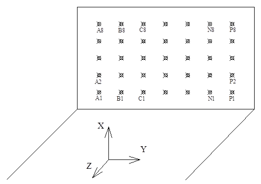
Pic 4.1 – Scheme of calibration range
The size of step in both axis is 0.4 m. The range has eight row with 14 marks in each row. Maximim distance of photographing is 14 m for this calibration range [9].
The sequance of camera’s calibration of cellphones:
- The calculation of approximate focus distance of testified camera with image;
- Photographing of calibration range. (pic. 2.2);
- Processing the results;
- Adjustment;
- Estimation accuracy.
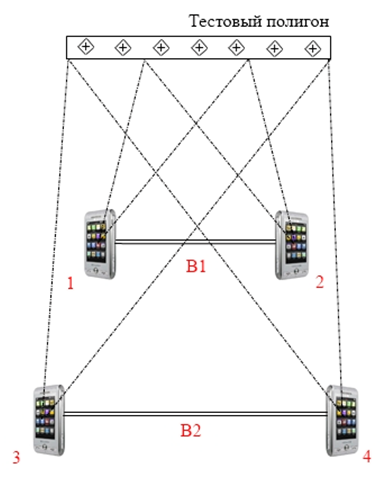
Pic 2.2 – Scheme of photographing of calibration range
For calibration cellphone LG GX-500 has been used. The matrix resolution is 3.0 Mpx (pic. 2.3)
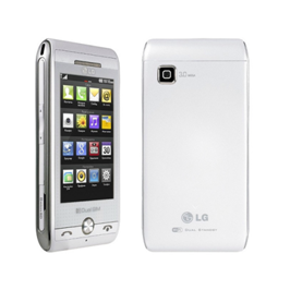
Pic 2.3 – Cellphone LG gx-500
Camera of this cellphone has autofocus mechanism. Maximum image’s resolution is 2048х1536 px.
For photographing the convergent case was selected with 100% overlaying of all images of stereopair. As result two sterepairs were taken (pic. 2.4, 2.5) from the different distances to calibration range from photohrahing basis – B1 and B2 (2.4 m and 2.92 m recpectively)
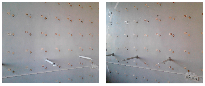
Pic 2.4 – Images from basis B1 (position 1 and 2)
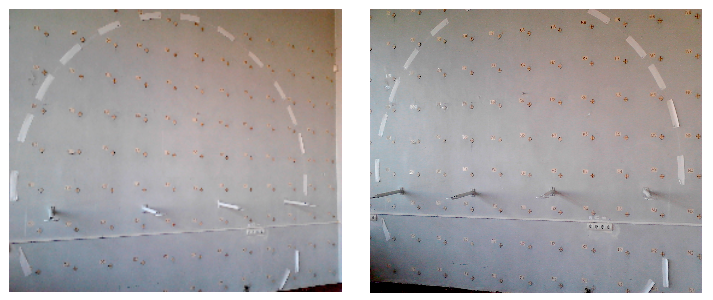
Pic 2.5 – Images from basis B2 (position 3 and 4)
Photographing was made from tripod with autostart to minimize the distorions, which led by the shift of image. Photographing was made with no flash in daylight.
These images were postprocessed in software DipEdit/Digitals – contrast and the size of pixel were justified. After this images were saved in TIF-format file.
For next work the passport data for camera and routes for every stereopair were created in software Block/Digitals.
Next processing was made in software Triangulation/Digitals.
Adjustment of results was made in the software for anaylitical triangulation BlockMSG, the results are parameters of systematics errors (20 coefficients) and the value of focus distance.
The result of correct calculation might be considered that has value of error of weight does nor exceed 1 mm, and the value of standard deviations on the base point are not greater than 2 mm in XY plane and in Z axis [9].
To analyze the field of distortions, which were eliminated with founded coefficients of systematic errors, surfaces were built. To build them need to use presented below polynims for axis X and Y [9]:
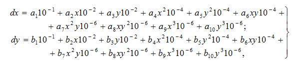
where ![]() the coefficients of distortions since 1 to 10 (adjustment data);
the coefficients of distortions since 1 to 10 (adjustment data);
![]() the coefficients of distortions since 11 to 20 (adjustment data).
the coefficients of distortions since 11 to 20 (adjustment data).
These values and sum of them will be used as the third coordinate for the surface, and aa plane coordinates might be used measured photocoordinates of one of the images. Build in the Surfer surface is shown on the pic. 2.6.
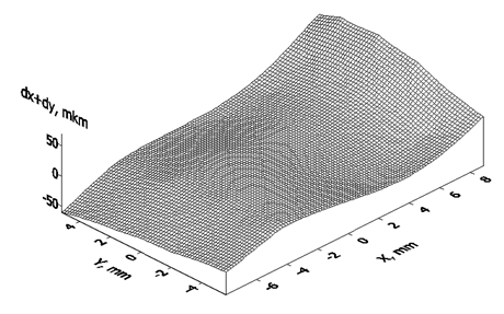
Pic. 2.6 – The surface of systematic errors
Maximum value of systematic errors is 70 mkm. Although , despite of this value is not big, the surface has systematic features.
Conclusion
These steps were executed in this master work:
- Definition of focus distance of camera of cellphone LG gx-500;
- Photographing of calibration range by the camera of cellphone to futher process;
- Measurements of digial images;
- Adjustment of results.
The focus distance of camera of cellphone LG gx-500 was defined. It equals 18.940 mm. Also the coefficients of systematics errors are found.
Table 1 – Coefficients of systematic errors
| № | Axis Х | Axis Y |
| 1 | 0 | 0 |
| 2 | -0.17827 | 0 |
| 3 | -0.04818 | -0,17827 |
| 4 | 0 | 0,04791 |
| 5 | -0.75026 | -4,67854 |
| 6 | 0 | 4,25962 |
| 7 | -19.45016 | 43,97805 |
| 8 | -20.50076 | -35,54581 |
| 9 | 110.25466 | 3,06295 |
| 10 | 1.93653 | -41,1906 |
The application of the camera of cellphone LG gx-500 for the measuremets is not possible, becouse of the values of systematic errors in such cameras reach the significal levels, and images does not have the needed levels of specification for qualified measuremens.
For futher work the calibraion will be processed for two another cameras of cellphones.
Sources
- Фотограмметрия (конспект лекций) / Корнилов Ю.Н. – Санкт-Петербург, 2006 – 172 с.
- Цифровая фотография для всех [Электронный ресурс].15.02.2013.Режим доступа: http://www.photoforall.ru
- Справочник ЖКХ. Дисторсия [Электронный ресурс].15.02.2013.Режим доступа: http://gkh-topograph.narod.ru/distorsio.htm
- Лабораторная калибровка цифровых камер с большой дисторсией [Электронный ресурс].17.02.2013.Режим доступа: http://www.stereo-pixel.ru/docs/pressa/2/kalibr.htm – Р.Н. Гельман, А.Л. Дунц
- Википедия [Электронный ресурс].12.02.2013.Режим доступа: http://ru.wikipedia.org/wiki
- Фотограмметрия [Электронный ресурс].17.02.2013.Режим доступа: http://photogrammetria.ru
- Международный научно-технический и производственный электронный журнал "Науки о Земле" №01-2011 от 14.08.2011 г. / под ред. Докукина П.А. – ООО «ГеоДозор» – 110 с.
- Методы учета систематических искажения аэроснимка. Самокалибровка [Электронный ресурс].20.02.2013.Режим доступа: http://www.masters.donntu.ru – Курков В.М.
- Методические указания к самостоятельной работе студентов по дисциплинам «Фотограмметрия и дистанционное зондирование»на тему «Калибровка цифровой камеры на основании снимков испытательного полигона»/ А.А. Шоломицкий, А.А. Лунев – Донецк, ДонНТУ, 2010, – 22 с.
- Конструктивная калибровка цифровой камеры / С.Г. Могильный, д-р техн.наук, проф., А.А. Шоломицкий, д-р техн.наук, проф., А.А. Лунев, канд.техн.наук, доц. (Донецький национальный технический университет).
- Brown, D.C., 1966. Decentering distortion of lenses. Photogrammetric Engineering, 32(3): 444-462.
- Brown, D.C., 1972. Calibration of close-range cameras. International Archives of Photogrammetry and Remote Sensing, 19(5) unbound paper: 26 pages, ISP Congress, Ottawa
- Brown, D., 1989. A strategy for multi-camera on-the-job self-calibration. Institut Fur Photogrammetrrie Stuttgart, Festschrift, Friedrich Ackermann, zum 60. Geburtstag. 13 pages.
- Ziemann, H. & El Hakim, S.F., 1982. On the definition of lens distortion reference data with odd power polynomials. The International Archives of Photogrammetry, 24(1): 123-130.
- Ziemann, H., 1986. Thoughts on a standard algorithm for camera calibration. Progress in Imaging Sensors, Proc. ISPRS Symposium, Stuttgart, : 41-48.
- Shortis, M.R. Snow, W.L. Goad, W.K., 1995. Comparative geometric tests of industrial and scientific CCD cameras using plumb line and test range calibrations. International Archives of Photogrammetry and Remote Sensing, 30(5W1): 53-59.