
Abstract
Content
- Introduction
- 1. Rationale of topic, the relevance of the research work
- 2. Objectives and expected results
- 3. Overview
- 3.1 Hydraulic hammers
- 3.2 Submersible hydraulic hammers with valve-spool fluid distribution
- 3.3 Disadvantage of this tools
- 4. Rationale of design
- 5. The developed mechanism
- Conclusions
- References
Introduction
Currently in Ukraine, as well as throughout the world, one of the major problems is water and water consumption. At the scientific conference at the Institute of Hygiene and Medical Ecology. AM Marzeev Academy of Medical Sciences of Ukraine, "Water in Ukraine: current status, problems and solutions," described the problem this way:
"The high level of anthropogenic impact on water bodies and the use of outdated technologies of drinking water treatment, do not allow to provide the population with quality drinking water.
The use of technology in the treatment of drinking water, chlorine ineffective coagulants and flocculants, the lack of sorption filters with activated carbon, and so leads to the ingress of water into drinking large amounts of inorganic and organic contaminants, the combined effect on the human organism, especially in the radiation exposure causes a real threat to the health of the nation.
In addition, drinking water from surface water bodies potentially unsafe in virological terms, since the technology of its preparation does not guarantee the removal of viruses from water. Underground waters of Ukraine, in particular, the deep water in most regions (Donbas, the Dnieper, Crimea) on quality does not meet the drinking waters, which is associated not only with the natural conditions of their formation, but the man made pollution, and therefore need to be cleaned ... "[7]
As the need arises in the search and development of new sources of water. For a more accelerated pace of drilling is necessary to improve and upgrade the drilling tool.
Master's thesis is devoted to the study of the valve group double-acting hydraulic hammer with differential piston to drill water wells.
1. Rationale of topic, the relevance of the research work
Drilling of wells for drinking and industrial water runs self-propelled units. Design features of these systems can not provide a rational load bits when drilling large diameter, which reduces the efficiency of the drilling process and its technical and economic performance, especially in hard rocks (granite, sandstone, limestone). One of the ways to intensify the drilling process is the use of hydraulic hammers, which would have played the role of shock pulse generator to increase the load on the bottom of the well. In this hydraulic hammer can work independently with a special chisel, and a supporting role when working with rock bits.
Thus, for the practice of drilling wells for water enough actual hydropercussion is to develop a mechanism that could be used for the intensification of roller cone drill bits, and for rotary-percussion drill bits with cutters. This will in the first instance to increase the technical and economic parameters of drilling, and the second - to reduce costs by using cheaper tools. In this context, efforts to improve hydraulic hammers for drilling wells for water is urgent.
2. Objectives and expected results
Purpose - to improve the design concept hydraulic hammers for drilling water wells, refining methods of calculation and the laws of its work, the development of practical design and demonstrate how its technology.
Objectives of the study:
- Analysis of the current status and the existing calculation methods hydropercussion mechanisms for drilling water wells.
- Development of improved design scheme hydraulic hammers for drilling water wells.
- Improved methods of calculating hydropercussion mechanism taking into account the peculiarities of its operating cycle.
- Improving the design hydraulic hammers for drilling water wells and demonstrate how its technology.
The idea of study: the use of hydraulic hammers mechanisms to intensify the roller cone drill, or a complete replacement for rotary impact.
The object of study: Hydroshock mechanisms for drilling water wells.
Subject of study: design and operating procedures at hydraulic hammers mechanisms for drilling water wells.
Possible results to be expected in the performance of their novelty and significance.
As part of the master's work is to get the actual scientific results in the following areas:
- The algorithm for calculating hydropercussion mechanism for drilling water wells.
- The design of an improved impact mechanism (at the level of the utility model) technology and demonstrate how it.
The value of the work is to develop the design and calculation methods hydropercussion mechanism to justify its design parameters and application technology.
Scheduled to participate in the Republican scientific conference of students, "Drilling". Submission to the contest of student research projects and applications for utility model.
3. Overview
3.1 Hydraulic hammers.
Known hydraulic hammers (А.С. №199000 СССР кл. Е02d 7/18, 7/10 опубл. 28.06.1967).[1]
Hydraulic hammers includes adapter 1, 2 inlet and outlet. 3 valves, sitting on a common hollow sleeve 4 having a sealing piston 5 and the spring-loaded rod 13, tubes 6 and 7 constituting the body.
Hydraulic hammers comprises a piston 8 with a collar 9, the cylinders 10 and 11 with top cover 12, the firing pin 14, a piston 15, a top 16 and bottom 17 and anvil runner valve 18.
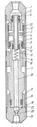
Figure 1 — Hydraulic hammers
The proposed hydraulic hammers intended to eliminate sticking drilling projectile yes, while it may be part of the drill and placed under the rock cutting tool.
During the drilling of the valve 18 is removed and the fluid supplied from the surface by the drill string is passed to the bottom of the well through a passageway 19 in the striker 14 and channel 20 in the anvil 17.
In the beginning of the hydraulic hammers cavity on top of cylinder 10 is blocked inlet valve 2 and is connected through the windows 21 and 22, with the well.
With increasing pressure fluid on the inlet valve 2 valve rod (parts 2, 3, 4 and 5) will go back down, as the sectional area of the valve 2 is greater than the area of the piston 5. At this point the spring-loaded rod 13 will be compressed and will begin lifting the striker 14. Simultaneously with the striker will be raised and the valve rod. At the moment of impact of the striker on the upper anvil 16 inlet valve 2 tion under the influence of a spring-loaded thrust washer fluid will open access to the top of the cylinder 10. At this moment, the outlet valve 3 will block port 21.
With increasing pressure fluid bone at the top of the cylinder 10 striker goes down, a blow to the bottom of the anvil 17 and moves the valve rod to its original position due to the engagement of the tab collar 9 piston 8.
3.2 Submersible hydraulic hammers with valve-spool fluid distribution
Hydraulic hammers consists of adapters 1 and 2, the intake valve 3 mounted on the hollow rod 4 exhaust valve 5, the compacted sleeve 6-cylinder housing 7, nut 8, with which the striker 12 is attached to thrust collar spool valve-block of a piston 9, spring 10, top 11 and bottom 13 anvils, cuffs 14 of the striker rod. In the initial position of the striker 12 under the action of its own weight is at the lower position, the inlet valve 3 is closed and the exhaust valve 5 - open. When a washing liquid is drawn down the hollow channel 4 and 12 g in the striker goes for the piston 9 and will take it up with the brisk. Due to the fluid pressure of the intake valve camshaft unit is held in place, so the spring 10 abuts the end of the traction and begin to contract. After going the way of free running and turn valves 8 nut face with spool 5 and move it to a distance of 0.5 Skl. Further transfer of energy is produced by the action of a spring and inertial forces. Thus the intake valve 3 is opened and the exhaust valve 5 used in the hole overlaps the casing 7 cylinders.
At the time of permutations spool valve-firing pin block 12 will strike the top of the anvil 11. As the drilling fluid through the annular gap and a hole in the open access to the cavity above the piston, the firing pin 12 starts to close. Free running when driving down the striker is S-Skl, and then capture the nut 8 thrust collar and open the exhaust valve 5. An inlet valve closes the flow of fluid. At the same time the firing pin 12 collides with the bottom anvil 13.
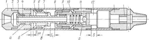
Figure 2 — Submersible hydraulic hammers with valve-spool fluid distributio
A distinctive feature of this is the lack of hydraulic hammers distribution head, which perform the function of the adapter 2 and the housing cylinder 7. Due to such a constructive solution could create a mechanism with a diameter 57 mm, without weakening the strength of the parts. This scheme can be designed vibrator 44 mm. The latter factors are important in connection with the widespread introduction of diamond drilling.
3.3 Disadvantage of this tools
Vibrators are described drawback is that they are designed to different values freewheel pin while moving up and down. Since the upstroke device group the first part of its travel passes together with the striker, and the second - at the expense of their own valve spring, the difference between the free moves up and down to their design is the difference between the values of total stroke valve group (which is to ensure the work exceed play striker when moving upwards) and compatible stroke and valve group on the upstroke (in fact, this is the free stroke of the striker when moving upwards). Thus, in the course of play down the striker will always be greater than the upstroke, so the speed of the striker when you hit the bottom of the anvil and the impact energy directed downward, will be less than the corresponding figures for the upstroke.
4. Rationale of design
The basis of the developed hydraulic hammers the task of improving the hydraulic vibrator, which, by reducing the free running of the striker when it is moved to the bottom of the anvil, the impact energy is achieved by increasing downward.
5. The developed mechanism
Developed multifunctional mechanism, which depending on the arrangement can be used both for drilling and for the elimination of accidents. As an example, the equipment hydraulic hammers to eliminate sticking in the well. [8]
The composition hydraulic hammer (Fig. 3) includes an adapter 1 with the axial and radial channels 2 and 3 connected to the valve box 4 with the exhaust holes 5. Valve Box 4-cylinder casing 6 rigidly attached to the top of the anvil 7. The body cylinder 6, the piston 8 is mounted with radial holes 9 which rod 10 rigidly connected with the striker 11 which has a shank 12 mounted in the hole bottom anvil 13. Upper and lower anvil 7 and 13 of the casing 14. In the valve housing 4 is mounted an inlet valve 15 adapted to move relative the hollow rod 16 which has a top ledge 17 above the inlet valve 15 and piston 8 coupled with a finger 18 which enables its movement restricted. The exhaust valve 19 with radial apertures 20 arranged above the piston 8, and between them movable relative to the hollow support rod 16, spring 21 is placed. In this case, the gap between the shoulder 17 and the adapter 1 is less than the gap between the exhaust valve spool 19 and a box of 4. The lower anvil 22 with radial channels.
Figure 3 — Designed by hydraulic hammer
Hydraulic hammer works in this way (for example, the elimination of the accident).
He goes down into the well after the occurrence of stuck and connects the lower anvil 13 with the stuck tool (not shown).
When hydraulic hammer drilling fluid is supplied, it enters the valve box 4 through the channels 3 in the top adapter 1 and a piston 8 through the central channel 2 at the top adapter 1, the cavity 16 and thrust radial openings 9. Due to the fluid pressure piston 8 begins to move upward together with the striker 11 connected thereto rod 10 and rod 16 is raised to a value of a stop shoulder 17 into the adapter 1, the inlet valve seat 15 is contained in the valve housing 4.
At the stroke of the piston 8 top compressed spring 21, and the liquid from the cavity of the housing 6-cylinder above the piston 8 is squeezed into the well through the radial ports 20 and exhaust ports 5. When the piston 8 will cover the distance S, then it would deal a blow to the exhaust spool 19. Last climbs up to the stop in the valve box to a distance of 4 Sk by the energy of impact and force of a spring 21. The exhaust valve 19 closes the exhaust radial channels 5 in the valve box 4 and opens the inlet valve 15. During this time, the firing pin 11 will be free running, which is equal to SB-S (it should be less for Sk to prevent re-strike on the closed slide valve exhaust), and hit the top of the anvil 7, which energy is through the housing 14 and the lower anvil 13 is transmitted to the tack-welded tool.

Figure 4 — Work hydraulic hammer
Because inlet valve 15 is open, the fluid enters the body cavity, the cylinder 6 above the piston 8, and by the fact that the working area on the piston 8 is greater than lower limit of the area of the shank 12, then a force, which forces the piston 8 to move down. Thus the intake valve 15 and exhaust valve 19 are in the upper position by the fluid pressure. As you approach the bottom of the anvil 13, the piston 8 finger 18 has a hollow rod 16 and moves it down. Rod 16 by the contact ledge 17 with the inlet valve 15 and returns it to the exhaust valve 19 to the initial position overlying fluid access to the body cavity above the piston-cylinder 6. During this time, the firing pin 11 will be free running, which is equal to the value of a, and strikes at the bottom of the anvil 13, which energy is transmitted to the stuck tool. Thus in order to play the striker, and accordingly, the energy of the up and down strokes were smooth enough to perform the ratio of Sb-S = a. The value of a should be less than for Sk stop to prevent the striker to strike the lower anvil.
Further work cycle is repeated.
Stuck eliminated by periodic shocks up and down, which generates a hydraulic hammer. In operation, the radial holes 22 in the bottom anvil 13 allow fluid circulation under shank 12, which is necessary for a functional mechanism in the case of hermetic stuck when the liquid from the bottom can not get under the shank 12 through the central bore in the bottom anvil.
Conclusions
Master's thesis is devoted to the actual problem, because in Ukraine as well as in the actual world is the problem of finding and developing new sources of drinking water and industrial water, and as a consequence of the development and improvement of methods and tools for drilling.
In the course of the master's work is planned computer simulation of the developed hydraulic hammers and analyze the data. Just to prove the design parameters of downhole samplers, perform a 3D-modeling and working drawings developed samplers.
When writing this essay master's work is not yet complete. Final completion: January 2014. Full text of the work and materials on the topic can be obtained from the author or his manager after that date.
References
- А.с. 199000 СССР кл. Е02D 7/18, 7/10. Гидравлический вибромолот / Г.И. Неудачин; Донец. политехн. ин-т (СССР). - № 1090034/29-14; заявл. 11.07.1966; опубл. 28.06.1967, Бюл. № 14. – 2 с.
- Коломоец А.В. / Предупреждение и ликвидация прихватов в разведочном бурении / А.В. Коломоец. – М.: Недра, 1985. – 220 с.
- Коломоец А.В., Ветров А.К. / Современные методы предупреждения и ликвидации аварий в разведочном бурении / А.В. Коломоец, А.К. Ветров. – М.: Недра, 1977.- 200 с.
- Козловский Е.А. / Справочник по бурению геологоразведочных скважин / Е.А. Козловский. – М.: Недра, 2000. – 712с.
- Калиниченко, О. И. Гидроударные буровые снаряды и установки для бурения скважин на шельфе / О. И. Калиниченко, П. В. Зыбинский, А. А. Каракозов. – Донецк : «Вебер» (Донецкое отделение), 2007. – 270 с.
- Парфенюк С. Н., Каракозов А. А./ Наукові праці Донецького національного технічного університету. Серія: Гірничо-геологічна. Випуск 11(161) - Донецьк, ДонНТУ, 2010. - С. 223-233.
- Актуальность и чрезвычайная острота проблемы обеспечения населения Украины качественной питьевой водой. [Электронный ресурс]. – Режим доступа: http://www.likar.info/zdorovoe....
- Гідравлічний вібратор: пат. 79599 Україна: МПК Е 21 В 31/113 / С.М.Парфенюк, А.А.Каракозов, А.А.Кадук, І.Д.Сагайдак; Донец. держ. техн. ун-т (Україна). - № u 2012 12764; заявл. 09.11.12; опубл. 25.04.13.