
Abstract
Content
- Introduction
- 1. Ungrounded or Isolated Neutral
- 2. Line to ground fault consiquencies in ungrounded systems
- 3. Negative affect on the overvoltage gate
- 4. Ways to solve the problem
- Conclusion
- References
Introduction
A short-circuit may lead to undesirable consequences in the network, such as insulation breakdown, damage to equipment, and, in some cases, create a risk to human life. To prevent this, there are several types of relay protection, which aimed at determining the damaged item and switching it off. The simplest method is to determine if the current value is exceeded over a given setting.
Ground fault current magnitudes depend on the system grounding method. Solidly- and lowimpedance grounded systems may have high levels of ground fault currents. These high levels typically require line tripping to remove the fault from the system. Ground overcurrent and directional overcurrent relays are the typical ground fault protection solution for such systems. However, high-impedance ground fault detection is difficult in multigrounded four-wire systems, in which the relay measures the ground fault current combined with the unbalance current generated by line phasing and configuration and load unbalance.
Ungrounded systems have no intentional ground. For a single-line-to-ground fault on these systems, the only path for ground current to flow is through the distributed line-to-ground capacitance of the surrounding system and of the two remaining unfaulted phases of the faulted circuit.
Most ground-fault detection methods use fundamental-frequency voltage and current components. There are also methods that use the steady-state harmonic content of current and voltage to detect ground faults [5].Another group of methods detects the fault-generated transient components of voltage and current [4]. These methods have limited sensitivity, because highresistance faults reduce the level of the steady-state harmonics and damp the transient components of voltage and current.
Ungrounded or Isolated Neutral
In an isolated neutral system (see Figure 1), the neutral has no intentional connection to ground: the system is connected to ground through the line-to-ground capacitances. Single line-to-ground faults shift the system-neutral voltage but leave the phase-to-phase voltage triangle intact.
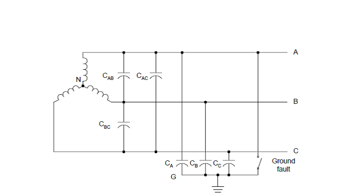
For these systems, two major ground fault current magnitude-limiting factors are the zerosequence
line-to-ground capacitance and fault resistance. Because the voltage triangle is
relatively undisturbed, these systems can remain operational during sustained, low-magnitude
faults.
Self-extinction of ground faults in overhead-ungrounded lines is possible for low values of ground fault current. At higher magnitudes of fault current, faults are less likely to selfextinguish at the fault current natural zero-crossing because of the high transient recovery voltage. Later, we discuss how a resonant-grounded system damps this recovery voltage rise, thereby increasing the likelihood of causing the ground fault to self-extinguish. Zero-sequence [6], or three-phase voltage relays can detect ground faults in ungrounded systems. This method of fault detection is not selective and requires sequential disconnection or isolation of the feeders to determine the faulted feeder. A sensitive, directional ground varmetric element is the typical alternative to sequential disconnection. These elements respond to the quadrature component of the zero-sequence current with respect to the zero-sequence voltage. Later we introduce a new directional element that uses the measured impedance as the measurand for differentiating forward and reverse ground faults.
Line to ground fault consiquencies in ungrounded systems
But not all types of damage are easy to detect. An example of such damage which is difficult to identify, can be an arcing line-to-ground fault in a network with isolated neutral. Line-to-ground fault does not alter the symmetry of the line voltages and does not make power disturbance of consumers. But the main danger of line-to-ground fault is that in the fault place intermittent grounding arc usually occurs, and if it burns for a long time, it can lead to the thermal effect and significant ionization of the surrounding space, which, in its turn, creates favorable conditions for the line-to-line faults. Also this grounding arc can lead to dangerous overvoltage (up 3.2 Uf) in the whole network. And if on separate parts of the network would be reduced insulation (e.g., due to pollution and moisture), the arc overvoltage may result phase-to-phase overlaps and equipment shutdown. But even in the absence of arc overvoltage, increasing of the line voltage can lead to the breakdown of defective insulation [1]. On the other hand the negative effects depend on the short-circuit current magnitude. If current value is significant, in this case, overheating has large magnitude whereas overvoltage has less value.
Arcing faults more dangerous than metal one, as impulse overvoltage occurs not only in the initial period, but during the whole time.
Figure 2. Line to ground fault
(animation: 9 frames, 5 cycles, 28.3 kilobytes)
Negative affect on the overvoltage gate
Also arc fault makes negative affect on the overvoltage gate. In case of the metal short-circuit, overvoltage gate limits surge only once - in the initial period. At the same arc faults this limiter works all the time, so it overheats. There were examples when the overvoltage gate was out of order due to arc faults. As practice shows, many of protection may not respond, i.e. not identify these kinds of damages, since the average value of zero sequence current usually does not reach the set point, and a distortion of the current and voltage waveforms of the zero sequence is quite sophisticate. So it makes determining of the current value, and discovering of the damaged place more difficult [2].
Ways to solve the problem
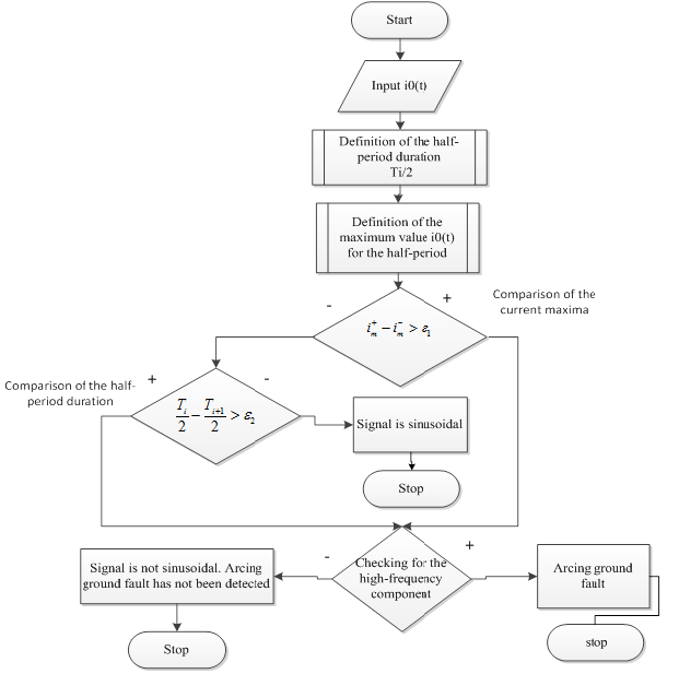
One way of solving this problem is to develop a method for the automatic analysis of the current waveform and the zero-sequence voltage.
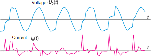
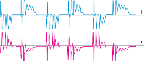
The figures show:
- Voltage waveform contains much less high-frequency components, so it is easier to record and analyze it;
-Current I 0 (t) may be interrupted for a while, and then the arc lights again;
-This current contains a large number of high frequency components [3];
Also for this type of short-circuit exists a set of features, which can help to identify this damage.
For earth short-circuit through unipolar arc:
1. Length difference between the even and odd half-waves should not be less than 1ms.
2. Ratio of the amplitudes of the even and odd half-waves 3U0 voltage should be at least 1.5
For earth short-circuit through bipolar arc:
1. Length difference between the even and odd half-waves should not be less than 1ms.
2. Ratio of the amplitudes of the even and odd half-waves 3U0 voltage should be less than 1.5
3. The maximum occurs during 1-2,6 ms after the transition through zero voltage 3U0 .
At the time of writing the essay master's work is not finished yet. Final completion: December 2014. The full text of the work and materials can be obtained from supervisor after this date.
References
- «Замыкание фазы на землю - предотвращение аварий и отказов в работе оборудования»
[Электронный ресурс] – Режим доступа: http://leg.co.ua...
- 2. Лихачев Ф.А. Замыкания на землю в сетях с изолированной нейтралью и с компенсацией емкостных токов. – М.: Энергия, 1971. – 152 p.
- Magazine "Новости Электротехники" №1(37) 2006 . article «Замыкания на землю в сетях 6–35 кВ, влияние электрической дуги на направленные защиты»
[Электронный ресурс] – Режим доступа: http://www.news.elteh.ru...
- Гельфанд Я.С. Релейная защита распределительных сетей, Москва: Энергоатомиздат, 1987 г.
- Федосеев А.M. Релейная защита электрических систем, Москва: Энергия, 1976 г.-560 с.
- Jeff Roberts, Dr. Hector J. Altuve, and Dr. Daqing Hou., WA USA Schweitzer Engineering Laboratories, Inc.
Pullman. Review of ground fault protection methods for grounded, ungrounded, and compensated distribution systems.
[Электронный ресурс] – Режим доступа: https://www.selinc.com...