Development of fault identification method in electrical system elements
Автор: Гребченко Н.В., Абрамов А.Г.
Источник: Всеукраинская научно-техническая конференция студентов: "Электротехника, электроника и микропроцессорная техника." ЭЭМТ-2014. Донецкий национальный технический университет.
Аннотация
Гребченко Н.В., Абрамов А.Г. Development of fault identification method in electrical system elements. В данной работе рассмотрены проблемы выявления замыкания на землю через дугу в сети с изолированной нейтралью, а также возможные последствия данного повреждения. Приведены примеры решения данной задачи другими исследованиями, и обозначен собственный вариант.
A short-circuit may lead to undesirable consequences in the network, such as insulation breakdown, damage to equipment, and, in some cases, create a risk to human life. To prevent this, there are several types of relay protection, which aimed at determining the damaged item and switching it off. The simplest method is to determine if the current value is exceeded over a given setting. According to this principle operate current cutoff and overcurrent protection. Other methods are based on using the relationship between voltage and current, which is realized by the distance protection. Other method, which compares values and phases of the currents at the beginning and end of the protected object, is used too, like in the differential protection.
Последствия замыкания на землю в сети с изолированной нейтралью
But not all types of damage are easy to detect. An example of such damage which is difficult to identify, can be an arcing line-to-ground fault in a network with isolated neutral. Line-to-ground fault does not alter the symmetry of the line voltages and does not make power disturbance of consumers. But the main danger of line-to-ground fault is that in the fault place intermittent grounding arc usually occurs, and if it burns for a long time, it can lead to the thermal effect and significant ionization of the surrounding space, which, in its turn, creates favorable conditions for the line-to-line faults. Also this grounding arc can lead to dangerous overvoltage (up 3.2 Uf) in the whole network. And if on separate parts of the network would be reduced insulation (e.g., due to pollution and moisture), the arc overvoltage may result phase-to-phase overlaps and equipment shutdown. But even in the absence of arc overvoltage, increasing of the line voltage can lead to the breakdown of defective insulation [1]. On the other hand the negative effects depend on the short-circuit current magnitude. If current value is significant, in this case, overheating has large magnitude whereas overvoltage has less value.
Arcing faults more dangerous than metal one, as impulse overvoltage occurs not only in the initial period, but during the whole time.
Also arc fault makes negative affect on the overvoltage gate. In case of the metal short-circuit, overvoltage gate limits surge only once - in the initial period. At the same arc faults this limiter works all the time, so it overheats. There were examples when the overvoltage gate was out of order due to arc faults. As practice shows, many of protection may not respond, i.e. not identify these kinds of damages, since the average value of zero sequence current usually does not reach the set point, and a distortion of the current and voltage waveforms of the zero sequence is quite sophisticate. So it makes determining of the current value, and discovering of the damaged place more difficult [2].
Пути решения данной проблемы
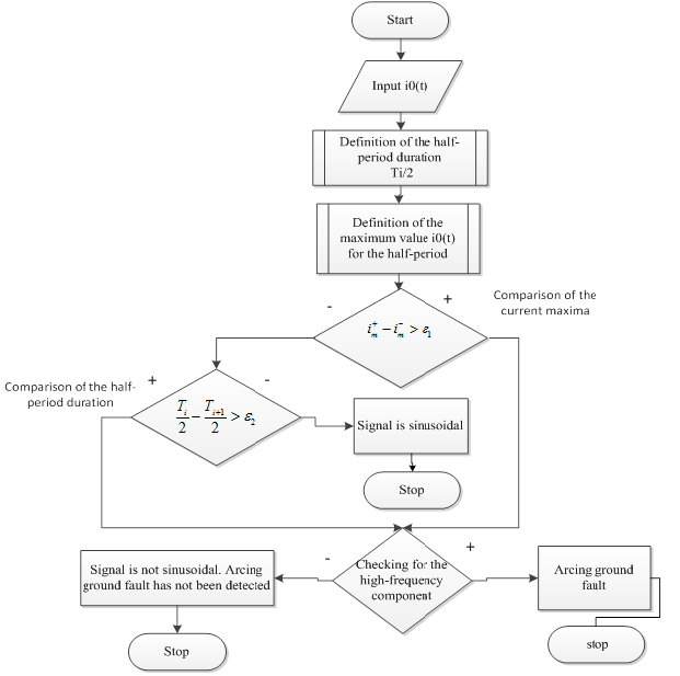
One way of solving this problem is to develop a method for the automatic analysis of the current waveform and the zero-sequence voltage.
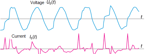
The figures show:
- Voltage waveform contains much less high-frequency components, so it is easier to record and analyze it;
-Current I 0 (t) may be interrupted for a while, and then the arc lights again;
-This current contains a large number of high frequency components [3];
Also for this type of short-circuit exists a set of features, which can help to identify this damage.
For earth short-circuit through unipolar arc:
1. Length difference between the even and odd half-waves should not be less than 1ms.
2. Ratio of the amplitudes of the even and odd half-waves 3U0 voltage should be at least 1.5
For earth short-circuit through bipolar arc:
1. Length difference between the even and odd half-waves should not be less than 1ms.
2. Ratio of the amplitudes of the even and odd half-waves 3U0 voltage should be less than 1.5
3. The maximum occurs during 1-2,6 ms after the transition through zero voltage 3U0 [2].
Список использованной литературы
1. «Замыкание фазы на землю - предотвращение аварий и отказов в работе оборудования»
[Электронный ресурс] – Режим доступа: http://leg.co.ua/knigi...
2. Лихачев Ф.А. Замыкания на землю в сетях с изолированной нейтралью и с компенсацией емкостных токов. – М.: Энергия, 1971. – 152 c.
3. Журнал "Новости Электротехники" №1(37) 2006. Статья «Замыкания на землю в сетях 6–35 кВ, влияние электрической дуги на направленные защиты»
[Электронный ресурс] – Режим доступа: http://www.news.elteh.ru...
4. Научные работы Донецкого национального технического университета. Серия: “Електротехніка і енергетика”, выпуск 79. - Донецьк: ДВНЗ «ДонНТУ», 2004 г.; Авторы:
Базилевич М.В., Сабадаш І.О., Шелепетень Т.М. «Автоматичне розпізнавання виду уземлення фази в електричній мережі з ізольованою та компенсованою нейтраллю»
[Электронный ресурс] – Режим доступа: http://ea.donntu.ru...