Ground fault monitoring in grounded AC systems
Автор: http://www.bender.org/
Источник:http://www.bender.org...
Аннотация
Ground Fault Monitoring in Grounded AC Systems. В данной работе рассмотрены процессы протекающие при замыкании на земли в сети с заземленной нейтралью .
Most technicians are very familiar with a current transformer based ground fault current relay. Even non technical personnel encounter them on a daily basis in public rest rooms protecting a wall outlet in a wet area. The operating theory behind the relay is as follows. A current transformer (CT) or “donut” is placed around the power wires leading to the protected load. It is important that hot and neutral wires are fed through the CT. This goes for both, single phase and three phase systems. One might come across a three phase system without a neutral, feeding a pump or an industrial motor. In this case the three phases only will be fed through the CT. Basic rule for three phase systems: If the neutral is being carried out to the load, feed it through the CT. If the neutral is not being used, then it may be left as is.
The current transformer will always read zero current in a healthy system even under a full load condition. In accordance to Kirchhoffs laws, Incoming and Outgoing currents will cancel each other out. Assume a 10A load connected to a 480/277VAC system. 10A will be fed from the source into the load, therefore 10A will have to return from the load back to the source. The CT will measure both simultaneously since it is placed around all conductors. The values were randomly chosen. Below is what the CT would see at a specific moment in time:
In accordance with the schematic below: 10A - 5A -5A= 0A for a healthy system
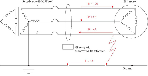
A ground fault (for this example, 1 A) will divert some of the current from the arrangement and bypass the CT via the ground wire, a frame or the building ground and return back to the source.
The new equation for the CT is now: 10A - 5A - 4A = 1A; 10 A go into the load, 9 A return to the source via the phase L2 and L3 and 1 A returns to the source via the ground wire. The CT will step the current (1A) down and forward it to the Ground Fault Relay (GFR). The GFR will then alarm when its set point has been increased. The GF relay in combination with a zero sequence CT will work in resistance grounded systems as well. It will run into its limitations in circuits where wave form modifying equipment, such as Variable Frequency Drives (VFDs) or rectifier components are installed. A more advanced technique is employed for DC circuits as well as circuits with variable frequency drives.