
Abstract
Maintenance
- Introduction
- 1. Relevance of a subject of research
- 2. Work purpose
- 3. Electrical power system
- 3.1 Electrical system
- 3.2 Configuration of a network
- 4.Systems of collecting and information transfer
- 4.1 Рhasor measurement unit
- 4.2 Wide Area Measurement System
- 5 Configuration definition on the elementary example..
- Conclusion
- References
Introduction
In the course of reforming of power industry of Ukraine, liberalization and deregulation of the market of the electric power a number of features was defined. In the conditions of the market relations the economic benefit and the price of electric energy became a priority for consumers. Appeared an isolation of networks and power lines from objects of generation. Thus, in a certain measure, the attention to such important problems, as reliability and safety of power supply is lost. Thus the role of system operators increases, there is a necessity of increase of operational discipline, providing appropriate levels of reserves of generating capacities and increase of carrying capacity of electric networks [1].
The problem of the state estimation (SE) of electrical power system (EPS) is solved on the basis of telemeasurements (TM). Values of TM are taked on power objects in a timepoint of t and are transferred by means of system of collecting and data transmission in the power supply system quick and information operating complex (QIOC). It is accepted that telemeasurements reflect a power supply system mode for this moment. As a rule, volumes of TM are insufficient for full observability of the scheme of EPS. Problems of deficiency of TM at EPS OS were repeatedly discussed [3], [4]. Besides, TM participating in the solution of a problem of OS, not always high quality because of gross blunders in some TM for a variety of reasons [2].
1. Relevance of a subject of research
Is defined by ncessity of further development of an automatic assessment of a condition of electric system. Important condition of functioning of national economy is development of the power branch which mission contains in production, transfer and electric power distribution between consumers. At the same time the condition of power systems is characterized by high level of wear of the equipment, big losses, outdated technologies. Thereof in a rating of efficiency of power systems Ukraine took place on the 72nd place among 105 countries. It demands development acceleration at innovative level. Ensuring updating of the equipment and technologies, minimization of losses and decrease in prime cost.
2. Work purpose
Work purpose is further development of an automatic assessment of a condition of electric system by the development of a method and algorithm of automatic detection of the current configuration of electric system at present time.
3. Electrical power system
3.1 Electrical system
Electrical system is a set of power plants, transmission lines, converter stations and electricity consumers for parallel work. E. s. has a general reserve and centralized operational control to coordinate the work stations, substations and networks. Often E.s. is identified with electric power systems (EPS) covering thermoelectric plant and heat networks. Power system along with centralized power provides centralized heat supply of cities and industrial centers. With the scientific and technical point of transition to the broader concept – "EPS" means considering not only the electrical part of the system and the electrical and electromechanical processes, but also keeping them connected with mechanical and thermal mechanical processes occurring in turbines, boilers, pipes.[6].
3.2 Configuration of a network
The configuration of a network is defined by a relative positioning of elements of lines, and the type of a network depends on category of consumers and degree of their reliability and survivability. Consumers of 1 category have to be provided with the electric power from two independent power supplies on two certain lines. They allow a break in power supply for the period of automatic turning on of the reserve power supply.
For consumers of 2 categories in most cases food on two certain lines, or on the two-chain line also is provided. As emergency repair of air-lines is short, rules allow power supply of consumers of 2 categories and on one line.
For consumers of 3 categories one line suffices. In this regard apply not redundant and redundant schemes.
Not the redundant – without reserve lines and transformers. Radial schemes concern to them (fig. 1, a), feeding consumers of 3 categories (sometimes 2 categories). Redundant schemes feed consumers of 1 and 2 categories. To them treat ring (fig. 1, b), with bilateral food (fig. 1. d) and difficult closed with nodal points of I, II, III, IV (fig. 1, e).
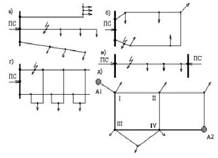
Fig.1. Configurations of electrical power networks: PS – substation; A1 and A2 – feeding knots (stations or substations) and) – a radial configuration; b) – ring configuration; c) – one-chain c) bilateral food; d) – two-chain main configuration; e) – difficult closed configuration.
In some cases construction of lines in redundant lines is carried out to two stages. One line is under construction and only with a loading growth to the design the second is constructed. Can be applied and the mixed configurations of power lines – redundant together with not redundant. Graphically electric networks represent in the form of schematic diagrams on which all elements represent the conventional signs connected among themselves in the same sequence, as well as actually.
Schematic diagrams of electric networks usually make in the most evident look that easily it was possible to track all power-supply circuits.
In fig. 2 the scheme which clearly demonstrates change of a configuration of a network at change of positions of switches
Рис. 2. Changing of a configuration of a network
Animation (7 shots, 5 cycles of repetition, 26,3 KB)
4. Systems of collecting and information transfer
In recent years digital technologies find the increasing distribution in systems of collecting and information transfer (SCIT). Synchronized vector measurements (phasor measurements) on all power supply system became possible thanks to tags of time of GPS in the seventies XX century and by means of computer technologies were originally applied in the field of digital relays. Today it is one of the most progressive methods of the measurement, allowing to receive the good accuracy and stability of measurements, the minimum delay of measured variables, to increase reliability of measuring system as a whole, and also to receive the functionality inaccessible to other types of sensors.
4.1 Рhasor measurement unit
PMU (phasor measurement unit) – the device measuring complex sizes of current and tension. Unlike traditional TI of measurement from PMU are synchronized on time through GPS, accuracy them higher and they arrive in points of collection of information of PDC (phasor data concentranor) in thousands of cuts a second whereas SCADA accepts one cut in some seconds.
4.2 Wide Area Measurement System
The power supply systems placed in large nodes, PMU together with SCADA system form – Wide Area Measurement System (WAMS). WAMS is an infrastructure in the network management process, designed under development and integration of information based on measurements [8]. WAMS increases possibilities of SCADA system: it includes collection of information, its processing and expeditious support, and is specially developed for updating of display of a power supply system for the purpose of its safety and reliability. WAMS — this device of registration of transients, as the criteria which estimates measure tension, current, power, a corner and frequency. All-system parameters from this list are only the frequency and a corner between two points of system.
5. Configuration definition on the elementary example.
Development of modern power industry goes on the way of expansion of application of renewables. In this regard the configuration of networks and influence of solar and wind power plants on working hours of electric systems becomes complicated.
The offered method of indirect definition of a condition of switches is based that calculations of various modes of system are carried out previously at known combinations of the switched-on and switched-off switches in electric system. Parameters of modes in the set control points of a network are thus fixed. Then for definition of position of switches measurement of parameters of a real mode in the set control points is carried out and on the basis of comparison of calculated and valid values of parameters of a mode in the set points position of all switches of a network is defined. As an example we will consider the following scheme of a site of a network:
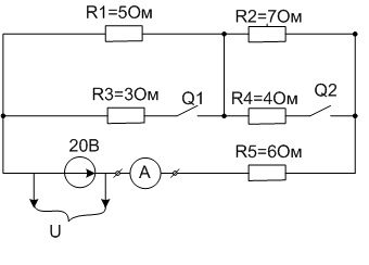
Fig. 1 – Scheme of a site of electrical power system
We will execute calculation of parameters of a mode of this site of a network for all possible combinations of two switches. Results of calculations are given in table 1.
Table 1 - Results of calculations at various combinations of switches

Thus, from table 1 it is visible that it is possible to define by the offered method indirectly a network configuration, i.e. in size of the general current position of Q1 and Q2 switches can be found. For reliable definition of position of switches it is necessary to provide high precision of measurement of value of current in control points.
Unlike the reviewed example, in real networks number of switches is more then two therefore for definition of a condition of all switches it is necessary to measure values of currents in bigger quantity of points at the same time. These points are defined depending on a concrete configuration and complexity of a network. [5].
Conclusions
The question of an assessment of the current mode of system is actual and it is offered to develop a method of automatic detection of a configuration of system for its development. Ultimate goal is increase of reliability of work of electric system and, in certain cases, improvement of quality of electric energy. It is necessary to develop algorithm and the program which will realize it. Then it is necessary to test on mathematical model to check operability of algorithm and the program. When writing this paper the master's thesis is not complete. Final end: December, 2014. The full text of work and materials on a subject can be received from the author or his head after the specified date.
References
- Обсуждение проблем надежности и безопасности в электроэнергетике // Энергетик. – 2005. – № 8. – С. 9-10.
- Кириленко О.В. Проблеми забезпечення надійної роботи ОЕС України в умовах реформування енергетики, Інститут електродинаміки НАН України, м. Київ.
- Гамм А.З., Голуб И.И. Наблюдаемость электроэнергетических систем. М.,Наука, 1990, 200с.
- Глазунова А.М., Колосок И.Н. Методика задания псевдоизмерений для обеспечения наблюдаемости схемы при оценивании состояния ЭЭС. Современные программные средства для расчёта и оценивания состояния режимов электроэнергетических систем. Материалы научно-практического семинара. – Иркутск: ИДУЭС. 2004 г.
- Черная Л.Г., Гребченко Н.В. Косвенное определение текущей конфигаруции электрической системы, Донецкий национальній технический университет, 2014 г..
- Веников В.Л., Мелентьев Л.А., Электрические системы, М., 1970.
- Школа для электрика [Электронный ресурс]. – Режим доступа: http://electricalschool.info/main/elsnabg/642-tipy-konfiguracii.html
- Jim Y Cai, Zhenyu Huang, John Hauer, Ken Martin. Current Status and Experience of WAMS Implementation in North America. IEEE/PES Transmission and Distribution Conference&Exhibition: Asia and Pacific. Dalian, China, 2005.
- Блог режимщика [Электронный ресурс]. – Режим доступа: http://blog.regimov.net/2012/power/project-wams-online.html
- Гамм А.З. Статистические методы оценивания состояния электроэнергетических систем. – М.: Наука, 1976. – 220 с..
- Глазунова А.М. Новые возможности для оценивания состояния электроэнергетической системы при использовании данных от PMU., Гришин Ю.А., Колосок И.Н., Коркина Е.С. ИСЭМ СО РАН, г. Иркутск.