Abstract
Christoph Legat, Jens Folmer and Birgit Vogel-Heuser Evolution in Industrial Plant Automation:A Case Study
Industrial plants are operated a long period of time. Hence, evolution of these plants is necessary to cope with technological developments or market requests. However, evolution cycles of disciplines involved in cooperative design of such plants are different. Therefore, further research needs to be investigated in order to provide an integrated variant and version management, i.e. evolution management, of such plants. As a first step towards solving this issue, this paper presents an abstract model for industrial plant evolution and analyses it using a detailed case study in the industrial plant automation domain.
I. INTRODUCTION
Industrial plants are typically operated for more than 15 years towards some decades. Thus, industrial enterprises are forced to evolve the plant due to several conditions, e.g. new technological developments or market requests [1]. Different disciplines, e.g. electrical, mechanical and software engineering, are involved cooperatively towards designing, constructing, maintaining and refining an automation system. Since design and construction of mechanical aspects is a time intensive process, a plant’s physical hardware is typically operated unmodified for many years. In contrast, software is altered much more frequently. Consequently, managing a plant’s evolution has to deal with diverging evolution cycles of involved disciplines [2]. Expert interviews conducted during the German research project BESTVOR1 highlight variant and version management as key factors for evolution management in industrial plant automation but mention a lack of tool support. Hence, in the next section, existing approaches for variant and version management are discussed to concretize existing lacks. Based on this investigation, an abstract model for industrial plant evolution is presented in section III. Subsequently, a detailed case study on industrial plant evolution is presented and analyzed based on the proposed model in section IV. The paper is concluded and summarized in section V.
II. RESEARCH ON INDUSTRIAL PLANT EVOLUTION
In order to understand variant and version management and to provide an evolution management for automation, existing approaches are analyzed in the following. A detailed analysis concerning evolution for industrial plants can be found in [3].
A. Variability and variant management
Variability for modular systems and models, as well as for product line approaches, is implemented by configuration mechanisms for composing the entire system out of smaller modules, e.g. [4, 5]. Classical product line/ family engineering (PLE/PFE), e.g. [6], create an underlying architecture of an organization’s product platform, e.g. [7], based on similarities and planned variabilities. Product variants are then derived from the basic product family. A lot of approaches have been published in the field of software PLE, e.g. [6], focusing on general foundations of variability management. Some approaches extend PLE towards product line evolution [6, 7, 8]. However, these approaches focus on a software view and, hence, lack in supporting interdisciplinary aspects.
To solve multidimensional evolution in industrial plant automation, variant and version management need to be integrated into PLE. In this field, approaches focus on product derivation [9, 10] and neglect the intermeshed variant and version management between derived products and product lines. They mainly consider software products [11], not taking the mechanical and electrical view on the system into account.
B. Versioning and configuration management
Concerning version management, most widely known approaches are Concurrent Versions System and Subversion, which aim at identifying conflicts while merging versions of text documents developed in parallel. However, automation engineering involves multiple disciplines and, thus, versions of discipline documents are developed concurrently. To make things worse, specific modeling languages and engineering tools are applied for these disciplines. Thus, metamodelspecific approaches such as [12, 13] are not applicable as they can only be applied to single modeling languages. The applicability of approaches independent from metamodels [14] for industrial plant automation needs to be evaluated.
Many approaches operate on a syntactic level comparing the syntactic structure of model versions for merging. Further approaches are operation-based and investigate the atomic operations leading to modifications in the model. These operations are considered for change tracing and conflict detecting; thus, a higher degree of automation during merging can be achieved, e.g. [15, 16].
III. PLANT EVOLUTION MODEL
For investigating industrial plant evolution, a plant evolution model is proposed in detail within this section. Firstly, we describe briefly the drivers forcing industrial enterprises to build and adjust their production facilities and identify the role of requirements on a plant. Secondly, an interdisciplinary engineering perspective and its relationships within plant evolution are presented (cf. Fig. 1).
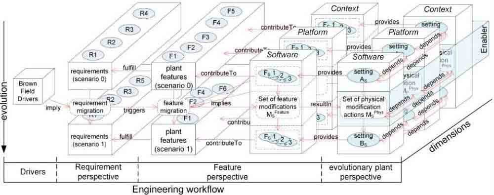
Fig. 1. Overall Plant Evolution Model
A. Evolution Drivers and Requirements on a Plant
Since industrial plant evolution is focused, the initial development of a plant as a green field project is not considered here and, thus, it is assumed that a plant already exists. As identified e.g. in [1], various different drivers for plant evolution exist, e.g. new technological developments, market dynamics, etc. From the engineering point of view, these evolution drivers imply a requirement migration: requirements stated to be fulfilled by an existing production system are changed to a set of requirements the plant under development shall fulfill. During engineering, these requirements are detailed.
B. Interdisciplinary Engineering: Dimensions of Plants
As described in section I, different disciplines are involved during plant engineering. In the following, we apply the terminology proposed in [3]. Technical system itself is addressed substantially by mechanical engineering and referred to as context dimension. The electrical hardware of a plant consisting among others of the controllers, sensors and actuators is called platform dimension henceforth. The third dimension is referred to as software dimension focused by software engineering, e.g. automation and control engineering. In the following, the subsumption of all parts of a plant consisting of a specific dimension is referred to as setting. After engineering a plant as green field project, a context setting AC, platform setting AP , and software setting AS build up the plant. These settings depend on each other due to interdisciplinary modules and compositions between modules.
C. The Feature Perspective: Properties of a Plant
In accordance to a variety of works, e.g. [17], we refer to properties of a plant as features. Since each dimension focuses on specific parts of the overall plant, each dimension provides a set of dimension-specific features. An example for a context feature is the maximum weight of a work piece a conveyor can transport since this depends basically on constructional aspects. The precisions and latencies of installed sensors are exemplary platform features. Software features might be the implemented interfaces or temporal behavior of the control software (e.g. worst case or minimum execution time).
Thus, the granularity of features can be either dimensionspecific (in case of provided interfaces) or abstract. All these features contribute to features of the overall plant, e.g. minimum throughput, maximum size of work pieces to be handled, etc. Analogously to dimension-specific features, features of a plant can also vary in granularity. The set of all possible features in each granularity is large in contrast to a set of relevant features. A feature’s relevance is given by its contribution to the whole plant’s relevant features. And, in turn, relevant plant features are predefined by requirements.
Considering an exemplary conveyor as objective plant, requirements might be the transportation distance and minimum throughput. As a result, the conveyor’s maximum throughput as well as the length of the conveyor belt (context feature) are relevant plant features. Consequently, in some cases, plant features might be equal to dimension features depending on the granularity of requirements. In case of the minimum throughput feature, different dimension-specific features have to be taken into account.
D. Plant Evolution: Modification of Settings and Features
As previously identified, drivers of a plant’s evolution trigger a requirement migration which results in an adapted set of requirements on the plant. In turn, relevant features of a plant are defined by the requirements on a plant. Consequently, a feature migration is required to address the requirement migration. If an existing plant can provide the feature set resulting from the feature migration, no adjustment of the system and, thus, no plant evolution is required. In most cases, if the evolution process is triggered, not all adjusted features can be fulfilled directly. For this reason, some modifications of the plant are required. In each dimension, i.e. context, platform, and software, a (probably empty) set of dimension-specific modification actions are realized to transform given settings within the three dimensions into modified settings. Each dimension comprises specific sets of possible modification actions. E.g. addition or removal of digital/analog devices is a typical modification action of the platform dimension whereas the replacement of a PLC type (e.g. upgrading a PLC) can be considered as a sequence of removing and adding actions in the platform dimension. Another typical action in this dimension is the configuration of a PLC, e.g. defining constant cycle times. Modification actions of the context domain might be addition and removal of context modules (e.g. mechanical parts). In contrast to these dimensions that deal directly with physical elements and, consequently, are defined by building blocks of the physical world, software is structured independently of physicality. For this reason, modification actions of the software dimension addresses dimension-specific building blocks, e.g. pieces of code, methods, functions, function blocks, interfaces, etc. Concluding, in each dimension, specific manifestations of modification actions deal with building blocks they are addressing. Furthermore, each of these actions can be regarded as a specialization of addition, removal, or configure actions. The latter can be seen as parameterization, adjustment, installation, etc. depending on the respective dimension.
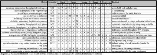
IV. CASE STUDY: EVOLUTION SCENARIOS
In this section, the evolution of a plant is discussed according to the evolution model introduced previously. We rely on a laboratory plant called pick and place unit (PPU) at the Institute AIS, cf. Fig. 2. In order to link our study to industrial practice, we will highlight the relation between the PPU and a use case in tank recycling industry throughout this section. Evolution scenarios which are discussed in detail in the following, its drivers and modification actions are summarized in Table I.
A. Initial Situation
Initially, a fictitious company TRC is operating a recycling working cell for tanks – called TRM henceforth – for automatically transporting tanks between two semiautomatic working positions. The following requirements were given when commissioning the TRM: i) at least three tanks should be handled in parallel and ii) only metallic tanks are used. Within the laboratory setup PPU, the TRM is represented by a stack for tank loading, a ramp as output storage, and a crane for pick and place operations between them. Tanks are represented by metallic chumps within the PPU. The stack has a maximum capacity of five tanks (context feature). After startup, the TRM separates a tank contained in the stack by moving a pneumatic cylinder which includes two binary position sensors (extruded or retracted). By extruding, a work piece is pushed to a pickup position. At the pickup position, a binary sensor detects the presence of a tank. If a work piece is available, the crane moves to the pickup position and intakes the tank using a vacuum gripper. Then the crane moves up, turns anti-clockwise by 90° towards the ramp where the tank is released. The tank slips down the ramp whereby the ramp has a capacity of three tanks (context feature). At this point the TRM stops processing if no further tank is available at the stack. Otherwise the process restarts automatically and the crane moves back to the stack. The overall plant is controlled by a PLC. The sensors and actuators are connected to terminal blocks where digital input and output signals are recognized and sent to the PLC. The control software is implemented using IEC 61131-3 standard. The TRM comprises a context feature, i.e. maximum capacity of three (cp. context features of stack and ramp). Since no other dimension-specific features contribute to the maximum capacity feature of the TRM, this context feature is equal to its corresponding plant feature. All sensors can detect each solid material (platform feature). For this reason, this feature contributes directly to the plant feature which fulfills the requirement that metallic tanks can be handled.
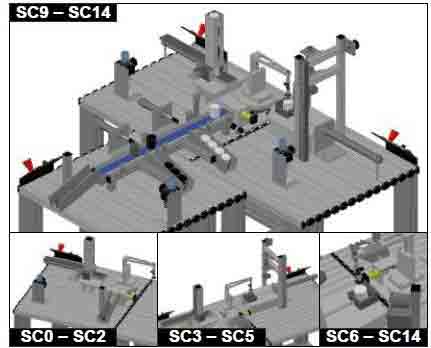
Fig. 2. Overview on Evolution Scenarios
B. Stamping module added
For traceability reasons (driver), it has been decided that hazardous material should be labeled (requirement migration). For this reason, a stamp is added to label metallic tanks (chumps). The stamp is located at position 180° (anticlockwise) of the crane and consists of two cylinders. One of them is initially extruded so that the crane is able to place the tank onto it, namely magazine. A digital micro switch in the magazine detects if a tank is available or not. As soon as a tank is available, the magazine retracts to position the tank under the stamp. The stamp moves down (extrudes), presses the tank for a while, and retracts (labeling process ended). As soon as the labeling process is ended, the magazine extrudes and the crane picks the tank placing it at the ramp. Due to the new stamp module context, platform and software are affected. For the crane, an additional digital position sensor is added to detect whether the crane is positioned at the stamp. This results in modification actions in all dimensions of the crane.
C. Inductive sensor for crane positioning
For identifying the crane’s positions, micro switches are used. When the crane touches such a micro switch, a digital signal indicates a specific position. Due to pollution, these mechanical contacts are characterized probabilistically. This leads to missing sensor signals and, consequently, the crane does not stop at a required position. Driven by the idea to increase TRM’s availability (requirement and plant feature), additional inductive sensors are installed which are more robust against pollution. Even if the inductive sensors are dirty, the electromagnetic field is still in progress, to detect metallic content at the bottom plate of the crane. The inductive sensors provide the same digital signal characteristics (operating voltage, control voltage) as the old position sensors. Hence, the software does not have to be adapted. Moreover, the geometrical size and the mechanical mounting are identical to the micro switches, thus, the context dimension is not affected. The replacement using inductive sensors only affects the platform. Hence, this relevant feature, using inductive sensors, is satisfying the same requirements of the last plant evolutions and even more the availability requirement.
D. Mechanical Buffer at Stamp Module
Due to the additionally mounted mechanical buffer, another metallic tank can be placed next to the stamp, even if the stamp is processing a metallic tank. During labeling a metallic tank at the stamp, the stack checks which kind of tank is available. If there is another metallic tank, the crane picks and places it on the mechanical buffer. Then, the stack changes to check the next tank. In case there is a plastic tank, the crane draws the plastic tank to the ramp and if there is a metallic tank, the crane has to wait until the labeling process is finished. The realized features affect every plant dimension because mechanical mounting (context) of the buffer has to be realized, a new position sensor for the crane has to be integrated (platform) and the implemented behavior of the crane has to be changed (software) to turn towards the mechanical buffer. The feature migration satisfies the given requirement of increasing throughput.
E. Adjusted sorting of work pieces
In this scenario the sorting order of work pieces is changed at the ramps. Now, there have to be mixed tanks in all ramps. This scenario only affects software because the behavior of the overall system is controlled by the PLC-code.
F. Potentiometer at the Crane
Up to this scenario the positioning of the crane is done by digital position sensors. To increase the accuracy and to avoid spending cables and terminal blocks, the digital sensors are replaced by a single analog sensor (potentiometer) which affects the context. The potentiometer has a specific analog value range. Hence, changes in the platform have to be made to process this signal by terminal blocks. Furthermore, the PLCcode (software) has to be adapted by changing the software module for the crane’s positioning. The software has to be able to handle the analog value.
G. EMC Resistance
After reorganizing the overall recycling plant, the crane’s positioning is characterized by unexpected random failures. Since the potentiometer for crane positioning is not electromagnetic compatible (EMC) but the TRM is now located next to a frequency converter, the driver for evolution is a technical reason independent of the TRM itself. To realize an EMC resistant crane positioning, the potentiometer is replaced by an incremental encoder which also has an analog signal but uses optical mechanisms to detect the crane’s position. The mounting of the incremental encoder is different from the potentiometer and, hence, the context has to be changed. A new terminal block has to be added to the platform, because the incremental encoder has a different electrical signal. At the end, the software has to be changed because the incremental encoder has a higher resolution and a higher value range in contrast to the former potentiometer.
V. SUMMARY & OUTLOOK
In this paper, an evolution model for industrial plant automation was presented. This model enables to formulate evolution steps initiated by drivers that trigger requirement migrations and subsequent feature migrations. It proposes to separate the engineering perspective into context, platform and software dimension in order to distinguish atomic modification actions during industrial plant evolution. Using a detailed case study, the applicability of the proposed model was shown.
REFERENCES
1. E. Westkamper, “Adaptable Production Structures,” in Manuf. Techn. for Machines of the Future. Springer-Verlag, 2003, pp. 87–120.
2. F. Li et al., “Specification of the Requirements to Support Information Technology-Cycles in the Machine and Plant Manufacturing Industry,” in IFAC Symp. Inform. Control Problems Manuf., Bucharest, Romania, 2012, pp. 1077–1082.
3. S. Braun et al., “Requirements on evolution management of product lines in automation engineering,” in Int. Conf. Math. Modelling, Vienna, Austria, 2012, pp. 340–345.
4. M. Svahnberg, J. van Gurp, and J. Bosch, “A taxonomy of variability realization techniques: Research Articles,” Softw. - Practice and Experience,
vol. 35, no. 8, pp. 705–754, 2005.
5. K. Pohl, F. van der Linden, and A. Metzger, “Software Product Line Variability Management,” in Int. Softw. Product Line Conf., Baltimore, US-MD, 2006, pp. 219–219.
6. K. Pohl, G. Bockle, and F. van der Linden, Software Product Line Engineering: Foundations, Principles and Techniques. Berlin, Heidelberg, Germany: Springer-Verlag, 2005.
7. E. A. de Oliviera et al., “A variability management process for software product lines,” in Conf. Centre Adv. Stud. Collab. Research, Toronto,
Canada, 2005, pp. 225–241.
8. P. Knauber, “Managing the Evolution of Software Product Lines,” in Int. Conf. Softw. Reuse, Madrid, Spain, 2004.
9. J. van Gurp and C. Prehofer, “Version management tools as a basis for integrating Product Derivation and Software Product Families,” in Int. Softw. Product Line Conf., Baltimore, US-MD, 2006, pp. 48–58.
10. R. Laqua and P. Knauber, “Configuration Management for Software Product Lines,” in Deutscher Software-Produktlinien Workshop, Kaiserslautern,
Germany, 2000, pp. 49–53.
11.L. Bendix, J. Graden, and A. Stahl, “A configuration management perspective on composing software product lines,” Department of Computer Science, Lund University, Lund, Sweden, Tech. Rep., 2009.
12. U. Kelter, J. Wehren, and J. Niere, “A Generic Difference Algorithm for UML Models,” in Softw. Eng., Essen, Germany, 2005, pp. 105–116.
13. L. Murta et al., “Odyssey-SCM: An integrated software configuration management infrastructure for UML models,” Sci. Comput. Programming, vol. 65, no. 3, pp. 249–274, 2007.
14. C. Bartelt, “Kollaborative Modellierung im Software-Engineering,” Ph.D. dissertation, Technical Unversity Clausthal, 2011.
15. M. Koegel et al., “Comparing State- and Operation-Based Change Tracking on Models,” in IEEE Int. Enterprise Distributed Object Computing Conf., Vitoria, Brazil, 2010, pp. 163–172.
16. E. Lippe and N. van Oosterom, “Operation-based merging,” ACM SIGSOFT Soft. Eng. Notes, vol. 17, no. 5, pp. 78–87, Nov. 1992.
17. K. Czarnecki, S. She, and A. Wasowski, “Sample space and feature models,” in Int. Softw. Product Line Conf., Limerick, Ireland, 2008, pp. 22–31.