Abstract
V. Fernao Pires, J. Fernando Silva SLIDING MODE CURRENT CONTROLLER FOR THE THREE PHASE SINGLE-STAGE AC/DC BUCK-BOOST CONVERTERS
This paper presents a sliding mode space vector αβ current modulator for three-phase single stage AC/DC Buck-boost rectifiers. Using this fast and robust control method, this type of converters draw near sinusoidal input currents with high power factor. A Proportional Integral (PI) controller can, then, be adopted to regulate the rectifier output voltage. The references of the sliding mode current controller are sinusoidal waveforms whose amplitude is modulated by this external voltage controller. Simulation and experimental results show the high power factor and low harmonic distortion obtained.
INTRODUCTION
In the last years, with the remarkable progress in the development of power semiconductor devices, more and more high frequency switching power source have been used in industrial and home electronic equipment. Usually, such systems use a combination of diode rectifier or phase controlled rectifier with a bulk capacitor as the primary dc source voltage. The advantages of these circuits are their inherent ruggednes and simplicity. However, due to combined effects of the smoothing filter and phase control action, the input current waveform becomes quite nonsinusoidal and phase shifted with respect to the sinusoidal input voltage. These drawbacks cause a number of problems in the power distribution network and other electrical systems, such as heating of core of transformers and electrical machines, large losses on the power lines, the supply voltage distortion, high reactive componets size and malfunctions in the electrical equipment.
To overcome the above shortcomings, in recent years AC to DC converters with input power factor have been proposed. The main function of these converters is to shape the input line current ir order to have a sinusoidal waveform and a near unity power factor operation. The Boost type [1, 2, 3] and the Buck type [4, 5, 6] AC to DC converters with input power factor have been the dominant design. Only few three-phase Buck-Boost type AC to DC converters with input power factor have been proposed [7, 8], despite advantages such as inherent short circuit protection, ruggedness and step-up/down output voltage characteristic. Therefore, this paper focuses on two three-phase single stage AC to DC Buck-Boost converters and their input current controller. To control the input line currents, a new control system based on a sliding mode approach with a space vector αβ current modulator is proposed. This current controller takes into account the real time perturbations of line voltages or load parameter [9, 10, 11, 12]. Moreover, since the sliding mode controller actively shapes the input line currents, it is possible to obtain a near unity power factor and input currents with nearly sinusoidal shape, even with high ripple in the DC inductor current. Therefore, these AC to DC current converters do not require a DC inductor with high inductance, reducing the size, weight and cost. As will be shown in this paper, this control scheme results in a very simple overall controller that can be implemented directly in hardware.
Some simulation and experimental results of two prototype converters are presented for demonstration.
THREE-PHASE SINGLE-STAGE BUCKBOOST AC/DC CONVERTER TOPOLOGIES
Fig. 1. shows the three-phase single-stage Buck-Boost type ac-dc converter with six switches, used to obtain high power factor and sinusoidal source currents. Since the switches must have bipolar voltage blocking capability, with devices such as punch-through IGBTs or MOSFETs, additional series diodes will be required, implying greater conduction loss. Fig. 2. shows the threephase single-stage Buck-Boost type ac-dc converter with reduced number of switches (four switches). Therefore, this topology has the advantage of decreasing the number of switches, thus increasing the reliability and the efficiency since the conduction losses in the switches are reduced.
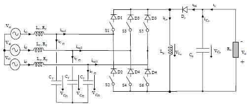
Fig. 1. Three-phase six switches single stage Buck-Boost AC/DC converter
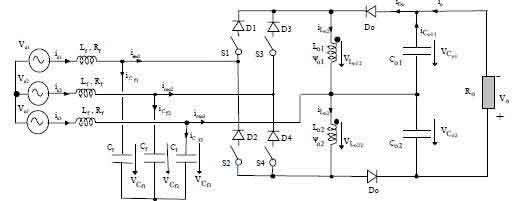
Fig. 2. Three-phase four switches single stage Buck-Boost AC/DC converter
MODELLING THE PROPOSED TOPOLOGIES
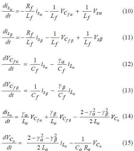
Switched state-space model of the six-switch rectifier Applying Kirchhoff laws to the circuit of Fig. 1. (using the displayed state variables), a simplified switched statespace model can be obtained:
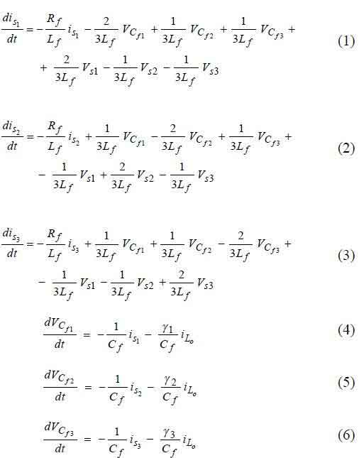
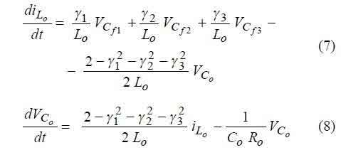
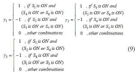
where the time-dependent variable γk represent the states of the switches of the kth, k∈{1, 2, 3}bridge leg, defined as:
Using the concordia transformation, the new simplified state-space model of the circuit of Fig. 1. is:
Switched state-space model of the four-switch rectifier using the displayed state variables of the circuit of Fig. 2., and using the concordia transformation, the following switched state-space model is obtained:
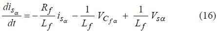
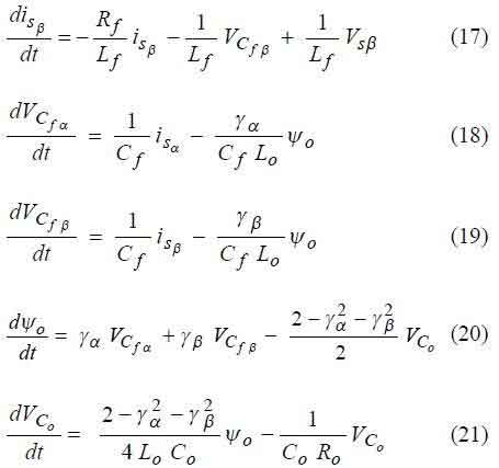
The developed models for the circuits of Fig. 1. and Fig. 2. will be used to define the sliding mode controllers.
SLIDIND-MODE CURRENT CONTROLLER
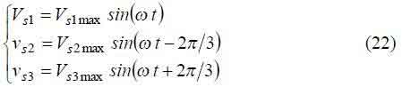
The main task of the current controller is to set the switching sequence for every switch of the rectifier, so that the input source currents are approximately sinusoidal and in phase with the respective line voltage. Defining the input source voltages as:
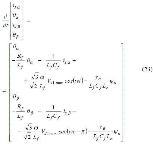
Considering isα and is&beta currents as the controlled outputs, the input-output linearization of the state-space model (10-15) gives the state-space equations in the controllability canonical form of (23).
From this new state-space equations, it can be concluded that isα and isβ currents have a strong relative degree of two [10] (as only its second-time derivative contains the control variables γsα and γsβ). The model (23) can be written as (25), using as new state variables the errors between the references and the actual variable values,
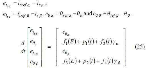
where f1(E), f2(E), f3(E), f4(E) are in general function of the error vector E=[eiSα, eθα, eiSβ, eθβ]T, while p1(t) and p2(t) are perturbations and γsα, γsβ are the control actions.
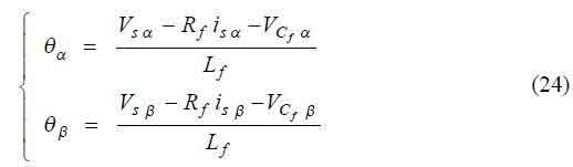
From the state space model in the controllability canonical form (25), and knowing the strong relative degree of each output variable ( isα and isβ ), it can be concluded that the sliding surfaces ensuring the robustness of the closed loop system are:
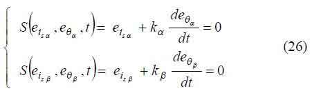
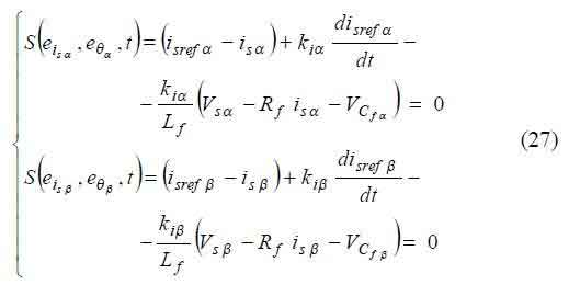
where kα and kβ are the parameter related to the time constant of the desired first order response of input source currents isα and isβ ( kα >0 and kβ >0 ). In practice the derivative of the currents can be obtained using the voltage across the inductors of the LC filter, therefore:
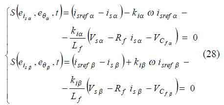
Since isref α and isref β are two sinusoidal signals shifted 90° a new simplified control law can be obtained:
The reaching mode and sliding mode stability conditions, or simple energy flow considerations (Tab. 1.), will give the switching strategy relating the switching laws (2) with the switching states γk.
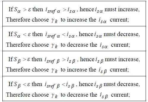
Tab. 1. Reaching and sliding mode stability conditions
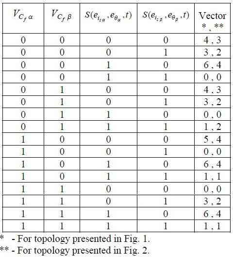
Tab. 2. Selected vector and switch according VCfα
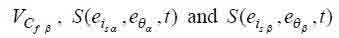
Depending on the states of the γk variables (representing the states of the kth switch of the rectifier), the bridge rectifier input currents can assume only 8 (for the converter with 6 switches) or 6 (for the converter with 4 switches) possible distinct states, represented as current vectors in the αβ reference frame (Fig. 3. and 4). To accurately select all the 8 or 6 available current vectors, from (2) it is essential to read two input line currents and two AC voltage capacitors in the αβ reference frame, and use two hysteresis comparators at the output of the current sliding mode controller and other two for evaluate the semiconductors bias. Therefore, the switches that must be on are listed in Tab. 2.
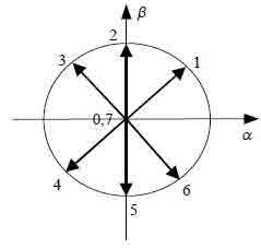
Fig. 3. Space-vector diagram of the converter with six switches
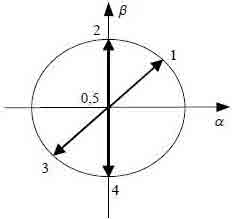
Fig. 4. Space-vector diagram of the converter with four switches
CONTROLLING THE OUTPUT VOLTAGE
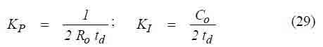
To control the output voltage of the proposed topologies, a proportional plus integral compensator (PI) is chosen, in order to have a stable system with good steady-state and dynamic response. As the frequency of the system is low (50Hz or 60Hz), and the current is controlled at high switching frequency, the rectifiers can be considered as current sources, with a small delay td. With this simplification, equations (29) give the parameters of the PI controller.
SIMULATED AND EXPERIMENTAL RESULTS
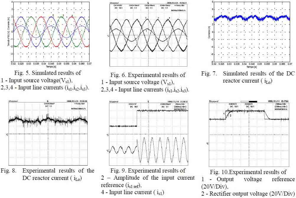
To verify the control algorithms, the design of the control parameters, and study the static and dynamic performances of the proposed topology, simulation results were performed. Therefore, the proposed topologies (with Co=Co1=Co2=10000uF, Ro=200 Om, Lo=10 mH, Lf=10 mH, Rf=1.5 Om, Cf=10 uF) were simulated using the software package "MATLAB / SIMULINK" [14]. The laboratory implementation of the proposed topologies allowed the validation of the theoretical results presented and the computer simulations. Figs. 5. and 6 show simulation and experimental results of the input line currents and input source voltage (Vs1max = 60 V) with the current controller parameters kα = kβ = 1.3e-4 and a hysteresis width of 0.001. These results show the almost sinusoidal input currents and high power factor provided by both rectifiers. The input source currents are dominated by the mains frequency sinusoid and the switching frequency components are greatly attenuated. Figs. 7. and 8 show simulation and experimental results of the DC reactor current iLo (in the topology presented in Fig. 1.). These results show that this converter with the proposed current sliding mode control works in continuos conduction mode. Fig. 9. shows the input line current in phase 1 of the topology presented in Fig. 2., and the amplitude of the current reference. As can be seen in this fig., for a step change in the current reference, there is a fast response of the current controller. Fig. 10. shows the experimental transient responses with a PI output voltage controller for the step change in reference value of output voltage, from 60V to 80V and back to 60V. This figure shows that it is possible to achieve a sufficiently fast voltage regulation with a good quality AC current with a high power factor. The behaviour of the output voltage is close to the theoretically expectable. Therefore, the PI compensator, with the parameters presented in (29), is adequate to be used in this topologies, as it presents a good steady-state and dynamic response.
CONCLUSIONS
Sliding mode controllers for input line currents of the three-phase single stage AC/DC Buck-boost converters were presented and tested. Phase canonical state-space models of the circuits were used to design the sliding mode controllers. The proposed input current control structure allow a near unity power factor operation, input currents with low harmonic content, fast dynamic response and robustness to parameter and load variations. With this current controller a simple PI controller can effectively control the output voltage of the rectifiers. Laboratory prototypes were implemented and computer simulations were performed. Experimental and simulation results show a close agreement and confirm the high power factor operation, fast response and low distortion.
REFERENCES
1. B. T. Ooi, J. C. Salmon, J. W. Dixon, A. B. Kulkarni, “A three-phase controlled-current PWM converter with leading power factor,” IEEE Transactions on Industrial Applications, vol. IA-23, pp 78-84, Jan./Fev. 1987.
2. A. W. Green, J. T. Boys, G. F. Gates, “3-phase voltage source reversible rectifier,” Proc. Inst. Elect. Eng., vol. 135, pt. B, no 6, pp 362-370, 1988.
3. John C.Salmon, “Techniques for minimizing the input current distortion of current-controlled singlephase Boost rectifiers,” IEEE Transactions on
Power Electronics, vol. 8, no. 4, pp. 509-520, October 1993.
4. Y. Sato, T. Kataoka, “State feedback control of current-type PWM AC-to-DC converters,” IEEE Transactions on Industrial Applications, vol. 29, no.6, pp. 1090-1097, Nov./Dec. 1993.
5. D. Vicenti, H. Jin, “A three-phase regulated PWM rectifier with on-line feedforward input unbalance correction,” IEEE Transactions on Industrial
Electronics, vol. 41, no. 5, pp. 526-532, October 1994.
6. R. Oruganti, M. Palaniapan, “Inductor voltage controlled variable power factor Buck type ac-dc converter,” IEEE Power Electronics Specialists Conference, June 1996, pp 230-237.
7. R. Itoh, K. Ishizaka, “Three-phase flyback AC-DC converter with sinusoidal supply currents,“ Proc. Inst. Elect. Eng., vol. 138, pt. B, no 3, pp 143-151,
May 1991.
8. C. T. Pan, T. C. Chen, “Step-up/down three-phase AC to DC converter with sinusoidal input current and unity power factor,” IEE Proc. Elect. Power Applic., vol. 141, no 2, pp 77-84, March 1994.
9. V. Utkin, “Sliding mode control design principles and applications to electric drives,” IEEE Transactions on Industrial Electronics, vol. 40, no. 1, pp. 23-26, 1993.
10. W. Gao, J. Hung, “Variable structure control of nonlinear systems: a new approach,” IEEE Transactions on Industrial Electronics, vol. 40, no. 1, pp. 45-44, 1993.
11. A. Groef, P. Bosch, H. Visser, “Multi-input variable structure controllers for electronic converters,” EPE Conference, September 1994, pp 30-35.
12. W. Gao, J. Hung, “Variable structure control: A Survey,” IEEE Transactions on Industrial Electronics, vol. 40, no. 1, pp. 2-22, February 1993.