
Abstract
Contents
- Introduction
- 1. Relevance of the topic
- 2. The purpose and the research problems, planned results
- 3. Elimination of voltage dips in the system of own needs
- 4. Mathematical model for the analysis of transients in system of own needs
- 5. Development of the program of calculation of transients
- 5.1 Description of the software environment and algorithm
- 5.2 Description of work of the program
- Conclusion
- References
Introduction
Own needs of thermal power plant – one of the most responsible parts of power supply of blocks. In modern systems of own needs the main loading are synchronous and asynchronous engines.
Owing to short circuits there are big voltage reductions or food breaks. At the moment of shutdown or a considerable voltage reduction at engines frequency of rotation quickly decreases. This process proceeding at low-power engines of a fraction of a second, and at large engines – to 10 with, is called vybegy. On run out gradually currents in windings, magnetic streams fade. While they did not fade completely, engines on run out work as generators, spending the energy of rotation reserved by them for maintenance in the network of residual tension not disconnected from them.
Reliability of power supply considerably raises, if for electric motors with driving mechanisms on which depend continuous work, self-starting is provided.
For definition of engines which can participate in self-start, it is necessary to carry out the analysis of the transients calculated with a fine precision.
This work is devoted to improvement of mathematical models and creation of the corresponding software products for calculation of transients and their further use in development of microprocessor automatic input of a reserve (AVR), for ensuring successful self-starting.
1. Relevance of the topic
Ensuring continuous work of power plant depends on creation of reliable system of power supply of own needs. At tension fall for engines of the most responsible production mechanisms self-starting is provided. Therefore the question of improvement of mathematical models and creation of the corresponding software products for calculation of transients, and also their further use in development of microprocessor AVR is actual.
2. The purpose and the research problems, planned results
The purpose of this work is development of mathematical model for research of transitional modes at decrease in feeding tension in system of own needs and transition to a reserve source.
Main objectives of research:
- Improvement of mathematical models for calculation of transients.
- Creation of the corresponding software products.
Object of research are methods and algorithms for modeling of mathematical model of transients at power plant.
As practical results development of software product in language C ++ and its further use at realization of algorithm of work of microprocessor AVR is planned.
3. Elimination of failures of tension in systems of own needs
In the most widespread ways of elimination of failures of tension today are:
- Creation of schemes of a reliable systems of excitement for increase of stability of operation of synchronous electric motors;
- Use of the scheme of usual AVR or automatic repeated inclusion. Usual AVR provides inclusion of a reserve food after shutdown of the introduction switch and after tension attenuation on reserved section. At the industrial enterprises it is necessary to provide no-failure operation of schemes of AVR on tension of 10 (6) and 0,4 kV;
- Introduction of special devices to perform high-speed AVR at a voltage of 10 (6) kV;
4. Mathematical model for the analysis of transients in system of own needs
In Figure 4.1 the schematic diagram of electric system with asynchronous and synchronous electric motors is represented.
Figure 4.1 – Initial schematic diagram of the electrical system
(animation: 5 frames, 6 cycles, 106 kilobytes)
The settlement scheme make on the basis of the set schematic diagram of electric system and equivalent circuits of its separate elements which with some simplifications are used in this work.
The settlement equivalent circuit is presented by resistance (active, inductive), resistance of switches, the KZ shunt, a grounding conductor and resistance of a stator of asynchronous and synchronous electric motors in capacity of 4000 and 6000 KW respectively.
For the description of the asynchronous engine we will use its double-circuit equivalent circuit which allows to consider rather precisely the phenomenon of replacement of a current in a rotor. Let's use a known method of receiving parameters of a double-circuit equivalent circuit on the basis of catalog data [2].
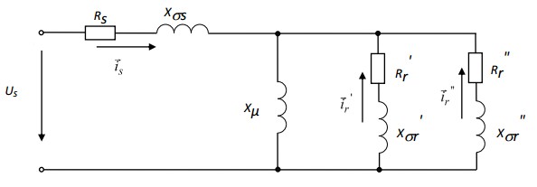
Figure 4.2 – Equivalent circuit AD
Salient Pole synchronous engines,for the purpose of possibility of ensuring asynchronous start-up are supplied with the starting winding which cores are put in polar boots of a rotor and electricly incorporate among themselves, and also to cores of the next polar boots. The so-called full starting winding in axes d and q and an excitement winding on an axis d is as a result formed.
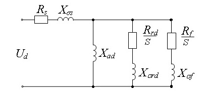
Figure 4.3 – Equivalent circuit of the salient pole synchronous engine on an axis d
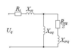
Figure 4.4 – Equivalent circuit salient of the pole synchronous engines on an axis d
Parameters of a winding of excitement:
Mathematical modeling of transients is made for instant values of currents and tension. For this purpose we will use Ohm and Kirkhgof laws according to which it is required to work out the differential equations for currents and tension of branches and knots of the set scheme. Algorithms of calculations we will make on the basis of matrix methods.
5. Development of the program of calculation of transients
5.1 Description of the software environment and algorithm
For development of the program the cross-platform program used Qt toolkit for software development in C ++.
It allows you to run written with its help software in most modern operating systems by simply compiling a program for each operating system without changing the original code. Includes all the basic classes that may be required in the development of software applications, ranging from the GUI elements to classes for networking, databases, etc.
Has also been used Qwt or Qt Widgets for Technical Applications – set Qt–widgets and helper classes needed to create graphical representations of numerical data.
5.2 Description of work of the program
For the calculation of the transition process have been previously found in the equivalent circuit parameters prefault mode.
The calculation will be carried out by the instantaneous values of variables, by means of numerical solutions of differential equations. Calculation step take equal 0.001 seconds.
For plotting transients in the system elements necessary to solve differential equations. Was used for this mathematical method of Runge - Kutta methods.
Implementation of Runge - Kutta methods in Qt:
void func_RK(Matrix &I, double t, double h, double Q1, double Q2, double Totk, double RQ1otk, double RQ1, double RQ2otk, double RQ2, double LQ1otk, double LQ1, double LQ2otk, double LQ2, Matrix &pr, Matrix &NvTR1, Matrix &NvTR2, Matrix &Tm1, Matrix &Tm2, Matrix &Nv_Q1,Matrix &Nv_Q2, double Um, double w, double Tkz, double Totk_kz, int KZ, double Rsh, double Rsh_KZ, double Lsh, double Lsh_KZ, Matrix &Nv_Sh_KZ, Matrix &R, Matrix &L, Matrix &P, Matrix &E, Matrix &Nv_E, Matrix &V, Matrix &Uuzl, Matrix &Uvet, Matrix &Dif, Matrix &RK)
{
int i;
double t2=t+(h/2), t3=t+h;
Matrix k1(I.rows);
Matrix I2(I.rows);
DD(I, t, Q1, Q2, Totk, RQ1otk, RQ1, RQ2otk, RQ2, LQ1otk, LQ1, LQ2otk, LQ2, pr, NvTR1, NvTR2, Tm1, Tm2, Nv_Q1, Nv_Q2, Um, w, Tkz, Totk_kz, KZ, Rsh, Rsh_KZ, Lsh, Lsh_KZ, Nv_Sh_KZ, R, L, P, E, Nv_E, V, Uuzl, Uvet, Dif);
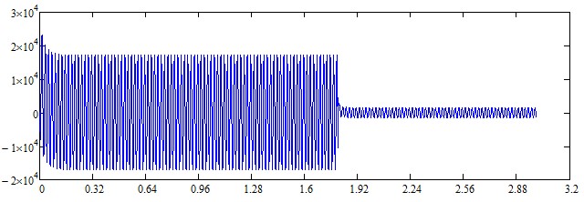
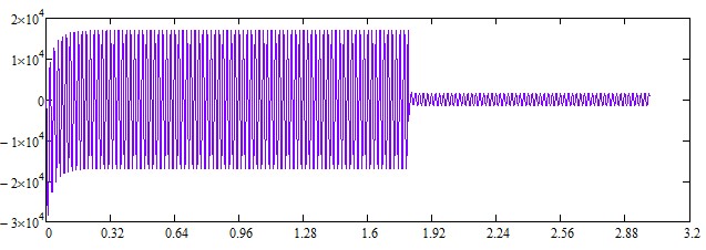
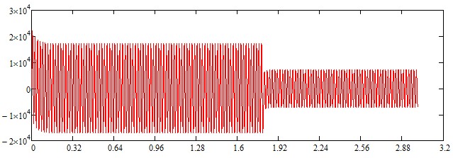
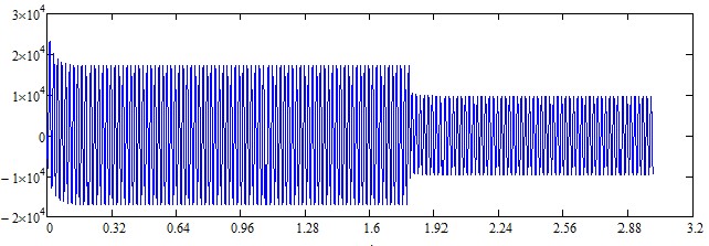
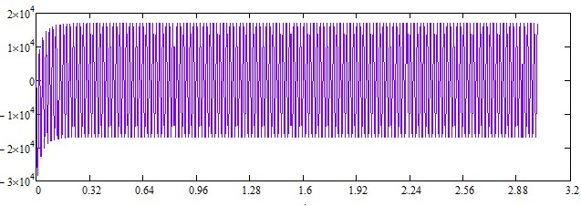
for(i=0;i { k1[i][0]=h*Dif[i][0]; I2[i][0]=I[i][0]+(k1[i][0]/2.0); } Matrix k2(I.rows); DD(I2, t2, Q1, Q2, Totk, RQ1otk, RQ1, RQ2otk, RQ2, LQ1otk, LQ1, LQ2otk, LQ2, pr, NvTR1, NvTR2, Tm1, Tm2, Nv_Q1, Nv_Q2, Um, w, Tkz, Totk_kz, KZ, Rsh, Rsh_KZ, Lsh, Lsh_KZ, Nv_Sh_KZ, R, L, P, E, Nv_E, V, Uuzl, Uvet, Dif); for(i=0;i { k2[i][0]=h*Dif[i][0]; I2[i][0]=I[i][0]+(k2[i][0]/2.0); } Matrix k3(I.rows); DD(I2, t2, Q1, Q2, Totk, RQ1otk, RQ1, RQ2otk, RQ2, LQ1otk, LQ1, LQ2otk, LQ2, pr, NvTR1, NvTR2, Tm1, Tm2, Nv_Q1, Nv_Q2, Um, w, Tkz, Totk_kz, KZ, Rsh, Rsh_KZ, Lsh, Lsh_KZ, Nv_Sh_KZ, R, L, P, E, Nv_E, V, Uuzl, Uvet, Dif); for(i=0;i { k3[i][0]=h*Dif[i][0]; I2[i][0]=I[i][0]+k3[i][0]; } Matrix k4(I.rows); DD(I2, t3, Q1, Q2, Totk, RQ1otk, RQ1, RQ2otk, RQ2, LQ1otk, LQ1, LQ2otk, LQ2, pr, NvTR1, NvTR2, Tm1, Tm2, Nv_Q1, Nv_Q2, Um, w, Tkz, Totk_kz, KZ, Rsh, Rsh_KZ, Lsh, Lsh_KZ, Nv_Sh_KZ, R, L, P, E, Nv_E, V, Uuzl, Uvet, Dif); for(i=0;i { k4[i][0]=h*Dif[i][0]; RK[i][0]=I[i][0]+(k1[i][0]+2.0*k2[i][0]+2.0*k3[i][0]+k4[i][0])/6.0; } } The program simulated various types short circuits in the networktheir own needs and diagrams of currents changes in the phases. Figure 5.2.1 – Graph of the transition process three-phase KZ (A, B, C) Figure 5.2.2 –Graph of the transition process two-phase KZ (A, B, C) As a result of research work have been collected and studied materials on issues related to the theme of master's work. In Qt programming environment has been developed a program for calculating the steady state networks, as well as modeled transient process for different types of faults. This master's work is not completed yet. Final completion: December 2014. The full text of the work and materials on the topic can be obtained from the author or his head after this date.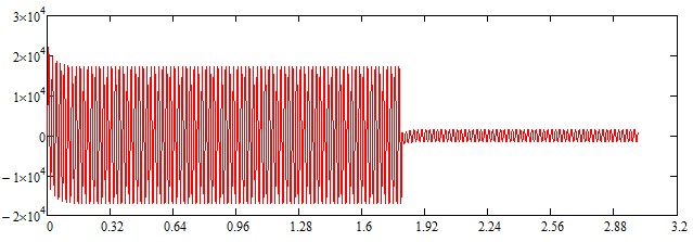
Conclusion
References