
Abstract
Plan
- Introduction
- 1. The definition of a hammer and its uses
- 2. Classification of hydraulic hammers
- 2.1 Classification of hammers by type
- 2.2 Classification by purpose
- 2.3 Standard group hammers
- 3. The principle of operation and the design of the hydraulic hammer high power
- 4. Mathematical modeling workflow hydraulic shock mechanism
- Conclusion
- List of resources
Introduction
Today it is hard to imagine any work associated with the destruction of solid material without the use of gidromolot a long period of time, the hammers are indispensable equipment in the construction industry and industry due to the fact that the range of application is very Cherokee powerful machines can destroy everything: with their help reveal asphalt-concrete cover, develop permafrost, split oversized, broken brick and concrete coating, and solve many other problems.
Hydraulic hammers have appeared in the sixties of the last century. The first test of hydraulic hammer was made in 1962 by the company Raymondв the United States during the vibropiling.

The aim of this work is to study the structure and principle of operation of a hydraulic hammer,acquaintance with the classification and application of hydraulic hammers,and development of a mathematical model of a hydraulic hammer high power to further define the optimal parameters for the operation of the hydraulic hammer.
1. The definition of a hammer and its uses
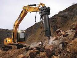
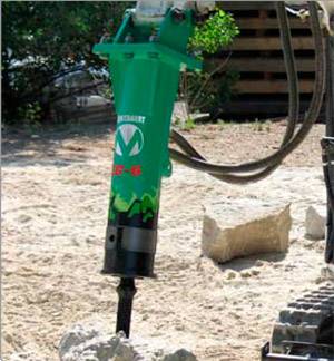
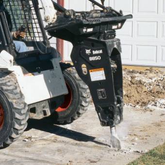
Hydraulic hammer working equipment for hydraulic excavators and loaders, used for processing of solid materials(rocks, soil, concrete)Gidromolot applied as an auxiliary attachments for the destruction of the rocky soil, concrete and reinforced concrete structures, frozen ground, opening of asphalt-concrete pavements and underground communications. [5]
Component parts of a hydraulic hammer are: head, dispenser, Luggage idling, Luggage stroke, pneumonia, network accumulator pressure line, line management control valve spool. Depending on the types of work performed hydraulic hammer is supplied various forms peaks: the cone, a chisel, a pencil and if it be equipped with different types of attachments, hydraulic hammer can be used for destruction of concrete structures or concrete walls. He is a removable cap for excavator, truck or tractor to perform the above mentioned works, which is connected to the hydraulic system of special equipment.[7]
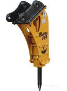
Drawing 1 – Hammer
Hydraulic hammer is used as a replacement of the working body for all models of excavators, hydraulic machinery of foreign and domestic production, as well as additional replaceable item trucks, stationary slaborazvityh machines. For each type of equipment is chosen its own model of a hydraulic hammer.
2. Classification of hydraulic hammers
2.1 Classification of hammers by type
By type hydraulic hammers share on the machine open and closed type.
The most effective and safe are hydraulic hammers with closed housing. They are low noise, reduce damaging effects on the base ekskavatorna category hydraulic hammers reduces the destruction of the impact of vibration on the excavator, thus prolonging the service life of the hydraulic hammer, but also of the machine on which it is installed.[6]
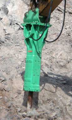
Drawing 2 – Hammers of open and closed type
2.2 Classification by purpose
On purpose hydraulic hammers are divided into three types: hydraulic hammers destroyers,the forging hammers and pile driving hydraulic hammers.
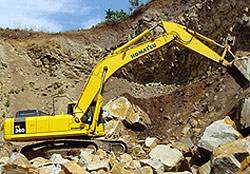
Hydraulic hammers destroyers are designed to disrupt and opening rocky soils, concrete and reinforced concrete structures, frozen ground.
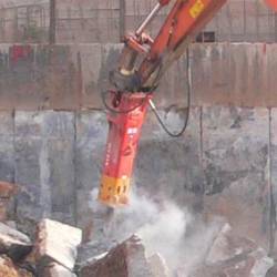

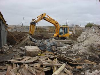
Drawing 3 – Hydraulic hammers destroyers
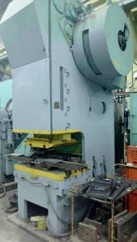
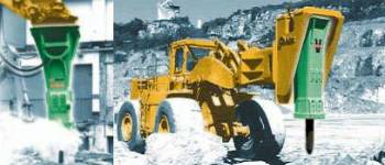
The forging hammers are used to perform stamping and forging operations.
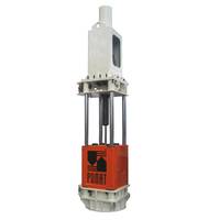
Pile driving hydraulic hammers are used for immersion of different pile components. [6]
Drawing 4 – Forging and pile driving hydraulic hammers
2.3 Standard group hammers
One of the main principles on which classify hammers,is weight and moshnosti this classification, the hammers are divided into light,medium and heavy.
Hydraulic hammers light class, hung on a small car, used primarily for the destruction of solid materials, road pavements and other similar works in limited amounts. Light breakers are designed for excavators weighing 0,35...tons
The hammers of the middle class is the most universal. They are widely used for the destruction of asphalt-concrete coverings, foundations, concrete and brick walls, construction and repair of roads, building of truboprovodnogo role such hammers play at carrying out of repair and emergency works on objects of municipal khozyajstvennye hydraulic hammers are applied in the work with bearing machines weighing 8...120 tons [4]
Drawing 5 – Hydraulic hammers light and middle class
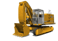
Hydraulic hammers heavy class is mainly used for heavy and large volumes of work, such as the demolition of buildings and various constructions, the breaking of frozen soils. Good workers, they are in quarries for crushing of materials of non-standard sizes. The use of hydraulic hammers heavy class is one of the alternatives of destruction of constructions with the help of the explosion, however, need to pay more attention to safety issues during their operation. Heavy hammers are not only those that have a fairly heavy weight ( over 1.5 tons), but also the fact that the energy of blow them up to big sizes ( from 4 to 20 kJ kJ). [2]
Drawing 6 – Hydraulic hammers heavy class
3. The principle of operation and the design of the hydraulic hammer high power
Hydraulic hammer used as attachments for excavators. The principle of operation of the excavator shown in Scheme 1.
Scheme 1. – The excavator
Consider the structure and principle of operation of a hydraulic shock mechanism high power, developed by the Department "Electromechanical systems", Donetsk National Technical University, the concept of which presents nigeen this striking mechanism I will consider in my work.
Drawing 6 – Hydraulic hammers heavy class
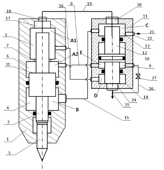
Hammer, a schematic diagram is shown above consists of a housing 1 inside which is located a striker 2 , a housing 1 forming the chamber 3 and the forward stroke flyback 4 . Firing pin coaxially in the housing 2 1raspolozhen tool 5 . Additional cavity 6 formed in the housing 1 is connected an opening 7 with direct flow chamber 3 and conduit 8 to the control chamber 9 of the dispenser 10 , consisting of a housing 11 , inside which is placed a valve 12 the housing 11 forming the pressure chamber 13 and drain chamber 14. pressure chamber 13 is connected with a channel 15 with the chamber reverse 4 . drain chamber 14 is connected to the camera channel 16 forward stroke 3 . at the top of the camera forward stroke 3 coaxially strikers 2 a cavity 17 for its hydraulic braking during the retrace . Hole 18 is connected to port 19 opening 20 for supplying the working fluid from the pressure chamber 13 through the lumen 17 direct flow into the chamber 3 . Striker 2 is in the cavity surface 21 of the piston 6 , the area that is larger than the opening 7 , connecting the chamber to direct flow 3 further cavity 6. At the top of the housing 11 of the dispenser 10 has an opening 24 for connecting chamber 14 with drain line 25 of working fluid discharge . The control chamber 9, the dispenser 10 is connected to the reset line 25 of the transfer tube 26 with the locking body 27.
The main elements of the hydraulic hammer are: the head, the tool and the switchgear. The principle of action is as follows: in the initial position, the hammer is in the lowest polozheniia closing stop valve, the pressure in the cells of the switchgear is set and the valve moves up,and the liquid enters the waste line and in consequence the pressure difference in the cells of the direct and reverse the hammer does idle until shank will not enter the appropriate cavity and zatormozit the difference of the squares in the cells of the direct and reverse head will move to the bottom of making a direct course,at the end of which will strike instrumentele switch switchgear Luggage forward stroke hydraulically connected with the vent line and die begins to sovershat reverse. The cycle repeats. [1]
4. Mathematical modeling workflow hydraulic shock mechanism
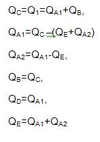
esignate working cameras of a hydrohammer as А1,А2,В,С,Е,D.
Find the pressure in all chambers:
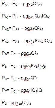
where α1, α2, α3, α4, α5,– ydraulic resistance channels connecting the respective chambers.
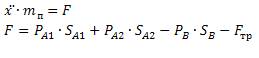
Fuel Q determined the speed of piston–striker and piston – valve

where V1 – speed of the piston-bojok,
V2 – velocity of the piston–valve,
S–area of work surfaces in the respective chambers.
Spending equation in the respective chambers for piston–striker:
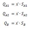
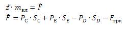
Spending equation in the respective chambers for piston–valve:
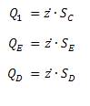
Balance equation expenses:
The equation of motion of the striker has the form:
Movable element node is the distributor piston valve , the equation of motion has the form:
Conclusion
The main objective of my further work is by mathematical modeling to analyze the concept in order to select the most efficient design and operating parameters for the operation of the hydraulic impact mechanism of high power.
List of resources
- Гидравлика, гидромашины и гидроприводы: Учебник для машиностроительных вузов/Т.М. Башта, С.С.Руднев, Б.Б. Некрасов и др. – М.: Машиностроение, 1982.-423с.
- Алимов О.Д. Басов С.А. Основы теории и расчета гидрообъемных виброударных механизмов. – Фрунзе; Илим, 1976.-25с.
- Гидравлический отбойный молоток [электронный ресурс]–Режим доступа -http://www.freepatent.ru/
- Гидромолоты легкого класса [электронный ресурс]–Режим доступа - http://www.os1.ru/article/road_equipment
- Гидромолот, навесное оборудование для экскаваторов и погрузчиков, запчасти и комплектующие к ним [электронный ресурс]–Режим доступа– http://gidromolot.tradicia-k.ru
- Классификация гидромолотов и их практическая применяемость [электронный ресурс]–Режим доступа– http://gidromolot.tradicia-k.ru
- Гидромолот.Общая информация.Принцип работы [электронный ресурс]–Режим доступа– tradicia-k.htm
- Гидромолоты легкого класса [электронный ресурс]–Режим доступа - http://www.os1.ru/article/road_equipment