
Abstract
NOTE: Summary staging is nature, as when it was created – April – May 2014, while the defense of master's work is scheduled for January 2015
Contents
- 1. Introduction
- 2. Relevance of the theme
- 3. The purpose and objectives
- 4. Review of existing studies
- References
1. Introduction
Improving quality and productivity of manufacturing core products, and therefore cost, is an actual problem of modern industry. Solving these problems, as well as related issues, ensure the competitiveness of products.
most commonly used method to obtain core product is the method of cold heading and stamping. This method has sufficient capacity in the amount of acceptable quality of received products. But given the demand and the amount used in industrial products of this type, the question increased productivity for manufacturing products is relevant even today.
Therefore, theoretical and experimental research aimed at the development, improvement and implementation of manufacturing processes for high-performance fasteners rotary lines, are important and relevant.
2. Relevance of the theme
It is now widely used fastening rod joining materials such as bolts, screws, screws, nails, etc. Used for the manufacture of separate processing equipment, which is inefficient, as it requires large cost of the production areas, transportation of parts from machine to machine, etc., to solve this problem is a highly automated production. Manufacture of these products on one production line will increase the technical and economic performance of their production , reduce costs and avoid transport costs.
3. The purpose and objectives
aim is to fold increase in productivity of the core product, by applying high–tech rotating equipment.
It is necessary to solve the following problem:
· To analyze the possibility of combining all operations of manufacturing products ranging from workpiece to organizing storage items .
· Preparation of high-performance and efficient process
· determining the applicability of the new kinematics in manufacturing core products or improving existing
· Development of the scheme rotary lines for the manufacture
· Designing new functional–oriented rotor line.
4. Review of existing studies
currently hosts a large number of studies on the development of rotors and rotor lines. Efforts of many scientists made ??a significant contribution to the development. Including LN Koshkin, IA Kloos et al
Currently, for the manufacture of these components used traditional equipment–cold heading machines discrete action that for a double stroke Upsetting slide provide the output of one product. Operating experience cold-stamping machines showed that their production depends on the length of the article. Since the length of the product determines the stroke of the ram , and hence the radius of the crank and connecting rod length, for the production of longer forced to slide to make longer stroke at lower speeds. Size range of manufactured parts as follows:
– Bolts – M2 ... M100;
– Nuts – M2 ... M100;
– Screws – M2 ... M56;
– Retaining rings : exterior and interior – 3 ... 300;
– Washers – M2 ... M100;
– Studs – M6 ... M100;
– Rivet – 2 ... 24;
– Splint – 1.6 ... 10;
Example, nameplate capacity of cold heading automata reaches 12 pcs/s for lengths up to 50 mm and with a length of 200 mm – 3 pcs/ sec. This is due to inertia, and dynamic loads and vibrations of the machine.
Basic material for the manufacture of parts such as bodies of rotation is usually different strength steel. For manufacturing grower - washers and Belleville washers uses a special spring steel. As a protective coating of zinc is used (Zn).
Development engineering and metalworking requires further improvement of technological processes and organization of production, increase its efficiency and increasing productivity on the basis of automation of production processes.
Stamping processes are widely used in various industries due to their high performance and cost–effectiveness.
Cold pressing was one of the most advanced technological methods of production; it has several advantages over other kinds of metal, both technically and economically.
Technically cold stamping allows:
1 ) To receive details of highly complex forms which manufacture or other processing methods impossible or difficult;
2) create a strong and rigid but light weight design parts with a small consumption of the material;
3) to receive interchangeable parts with high accuracy dimensions, without subsequent machining.
Economically cold stamping has the following advantages:
1) economical use of material and relatively little waste;
2) a very high-performance equipment, using mechanization and automation of production processes ;
3) mass production and low cost of manufactured products.
Greatest effect of the cold forming can be achieved with complex technical issues at all stages of pre–production, starting with the creation of technological designs or shapes of parts, allowing them to cost-efficient production.
Cold forging combines a wide variety of operations that may be organized by technology in - Office.
By the nature of the deformation
cold forming is divided into two main groups: the deformation of the material division and plastic deformation.
First group comprises deformations which lead to local separation of the material by shear and separating one part from another. Group plastic, deformation includes cold forming operation to change the shape of bent sheet metal parts and hollow.
There are four main types of deformations cold stamping:
1) Cutting–separation of one part of the material from each other in a closed – or open–loop mu;
2) flexible – the transformation of the slab into a curved detail;
3) hood – the transformation of the slab in the hollow part of any shape or further change its size;
4) forming - change form part or workpiece by local deformations of a different nature.
Each of the main types of cold forming deformation is divided into a number of separate specific operations, characterized by feature and purpose of work and the type of stamp.
by performing stamping several separate operations in most cases economically disadvantageous, thus methods generally used combined punching simultaneously combine two or more of these deformations and the individual transactions. In addition, the production uses assembly and stamping operations, based on the application of strain bending, forming or folding.
Combined punching is overlapping in one die two or more technologically different stamping operations.
When stamping small parts in fast presses in various industries, including instrumentation, precision mechanics, electrical engineering, electrical engineering, in the manufacture of consumer goods, etc. – basically use a combination of stamps and serial combined action. Each of these types of stamps has its advantages and disadvantages, their uses [1].
In combined punching dies all operations are performed by shearing the working elements of the stamp without indexing tape. The accuracy of the size of the stamped parts will be determined by the accuracy of performance punch and conditions of its operation.
In cases where the combined action of combined dies you - cutting contour with punched holes, a high accuracy of the arrangement of the outer contour to them. However, in successive dies possible to combine a large number of transitions in one prefecture die (10), while in combined die typically combines two or three transition, and therefore in this case is not always possible to completely eliminate the subsequent punching operation.
With automatic stamping presses for high-speed and high–volume with mass character of production generally tend to follow the complete elimination of stamping operations manual feeding piece blanks. Otherwise sharply reduced economic efficiency of this method of forming high due to the necessity of automation filing piece blanks, which is a very difficult task, because it requires special and punching in an automatic cycle on high–speed presses, machines with a large number of strokes per minute, so the tape is beneficial and of case conveyor belt mass is small, the inertial forces are negligible, and it can move very quickly, thus reducing the time of presentation.
For example, by pressing a flat parts in the tape at the present time many details of products manufactured on high–speed presses machines with the number of moves to 500 ppm and above, while co– accommodating stamps and stamps with vane operated by switching to high-speed presses machines with the number of strokes per minute 200-300.
The disadvantages of stamps combined action with spring and rubber pullers include reverse PEM felled de hoists in the tape, the difficulty of removing parts of the tape and sticking them to the stripper plate, making it difficult working conditions die.
In cases where combined design allows you to remove the die stamped parts to fail, creating favorable conditions for increasing the rapidity of the press. Successive punching a tape mainly produced small parts (10-50 mm) and small (10 mm) size. In some cases, consistent flat parts stamping their dimensions are 200-250 mm. In the combined action of the dies is possible to produce large parts. Minimum Annual Production of parts in which the costs of paying off the combined stamp sequential action can be determined by the method proposed V.P.Romanovskim [1].
Based flowsheets consistent punching that determine the type and design stamps sequential actions consistent stamping subdivided into a number of types of species In sequential stamping shown in FIG. 65, there is also cutting the slab on one of the first items on the transfer of its formative transitions slide gate or revolving mechanism.
From the species in Figure 1.1 serial punching tape for automatic stamping presses in fast at high strokes per minute are preferred: a, b and e, in which the office of the finished part of the tape is made on the last step, which increases the reliability and stability in the stamp.
Cutting contour on one of the first transition to the transfer slab on bending, forming and other operations in many cases carried out at an elevated number of moves the press, but the possibility of a significant increase in the number of moves at the same time limited, as no time to operate the actuator die, which leads to its premature failure.
Consequently , the question of at what those moves should punch press this or that detail when translating it into a high-speed stamping, need to be addressed consistent with possible technological schemes of its manufacture. It is quite clear that the greatest number of moves the press will take place at the cutting flat parts to fail.
Following describes a number of original designs of stamps, found use in cold pressing production enterprises that have adopted automatic stamping pa-speed presses.
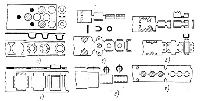
a - cutting the finished part in the last position of the stamp; b - length of the finished part from the tape in the last position; a - a strip of blank tape after a preliminary bending or molding; g - blanking on a contour in the first position with a stamp in her tape for subsequent transmission to formoizmenyayuschie position; d - workpiece segment on one of the first positions consistent with flexible positions on the last; e - incomplete clipping circuit parts with subsequent segments or fragments items from tape
With automatic stamping small parts in fast presses are widely used stamps combined with vane-automatic mechanisms [2]. Stamps- machines with E - vane mechanism are combined stamps consecutive action. Getting ready details such stamps is one of the most progressive methods of cold forming.
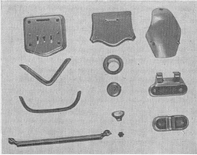
Fig. 1.2 shows the details of which are produced on stamps hinged mechanisms. Consider the mechanism and operation of several types of automatic stamps hinged mechanisms.
Stamps – machines with one slide gate. Figure 1.3 shows the design of the stamp, the proposed RA Dolgopolov, hinged on redeployment carved billet molding matrix. Stamp is designed for the manufacture of items of mass production (jacke suitcase).
This stamp is cutting and hood - molding parts in one stroke of the press.
Stamp works as follows. When you press down the slide during one wedge gate affects the roller 2 and gate 3 assigns to the extreme left and the wedge liner 4 affects the roller 5 and 6 Perekryvatel removes the rightmost position. As the lowering of the slider 7 knocks the punch workpiece clamping and using 8 puts it on the bottom plate 9, on the right slide, the end of which is shaped as a half blank contour .
During idling gate and Perekryvatel exempt from operating on their wedges. Under the action of the spring gate takes the workpiece onto the forming matrix 10 and Perekryvatel moves to the leftmost position and prevents the fly from the die blank.
With subsequent stroke cycle of the stamp set, which is done when the above-described kinematics of movement, but at the same time cutting occurs hood – molding parts to fail.
When working described Blanking punch is lowered into the matrix at a depth of 9–10 mm, which is necessary for a proper pre–cut blanks laying on the ground floor ( second tier) stamp. This is the specificity of stamps hinged redeployment.
Operation described stamp is on the crank press force of 25 tons of industrial type at 215 strokes per minute, equipped with a universal wedge- feed roller design R. A. Dolgopolov. Before the upgrade, the press was operated at 120 strokes per minute slide .
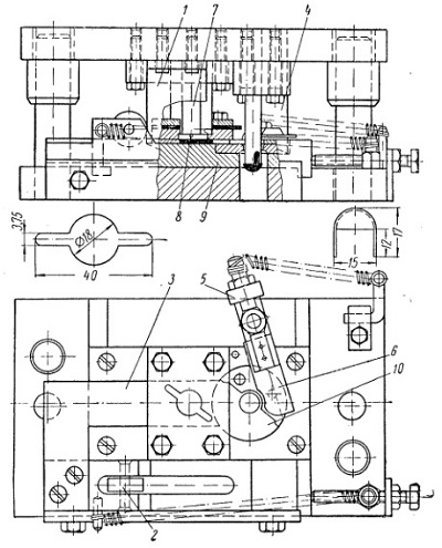
Prior to the implementation described stamp when executing in a separate molding die, the complexity of manufacturing jacke suitcase was 1.51 h per 1000 pcs., after the introduction of the same - 0.33 hrs
Due to the fact that the machine is first class, which is the method of cold press, characterized by intermittent treatment cycle, the only way to increase performance is to reduce the cycle time, ie increasing rapidity press. And this leads to a high-speed operating mode, which is characterized by large vibrations, loud and harmful to workers noise.
Currently mechanical presses usually have a considerably greater number of strokes per minute earlier than the production media. This applies especially to small presses efforts designed for cold pressing of the web material. Increase in the number of moves the press while using automatic feed the formed material is essentially the only way to improve their performance.
Since cold – Upsetting machines are machines class 1, in which processing and transportation are not aligned. Because of this, there are idling. To improve performance, it is necessary to reduce idling, and it can achieve an increase in the number of moves, which causes an increase in velocity, acceleration and inertia forces moving parts press that for certain values ??of their harmful but may affect the stability of the joints parts reciprocating motion. In low–speed presses no practical need for strict balance rotating parts; in fast is it necessarily as an imbalance in the light shafts, gears and other rotating parts can cause unacceptable vibration press.
In high–speed presses with the number of strokes per minute , more than 600–700 sometimes not enough to produce only static balancing of parts; dynamic balancing is necessary to press it to prevent vibrations. Hence, the design and manufacture of high–speed mechanical presses associated with a number of additional factors that can not be taken into account in the production of low-speed machines.
References
-
Бобров В.Ф. Основы теории резания металлом. - М. Машиностроение 1975.– 344с.Артоболевский И.И., Ильинский Д.Я. Основы синтеза систем машин автоматического действия. - М.: Наука, 1983.– 278с.Ищенко А.Л. Разработка технологического и структурного обес-печения проектирования высокопроизводительных процессов и систем сборки непрерывного действия. Дис. на соис. канд. техн. наук - Донецк, 1999.– 200с.